This thread has been locked.

If you have a related question, please click the "Ask a related question" button in the top right corner. The newly created question will be automatically linked to this question.

IWR1443: IWR1443 spurious spectral peaks

Part Number: IWR1443
Other Parts Discussed in Thread: LP87524-Q1,

Hi,


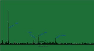
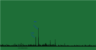
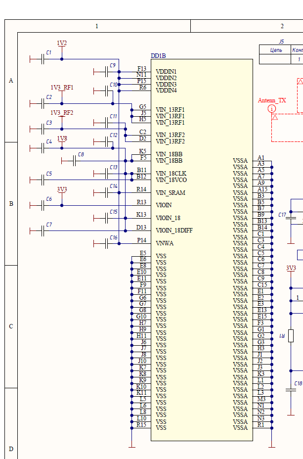
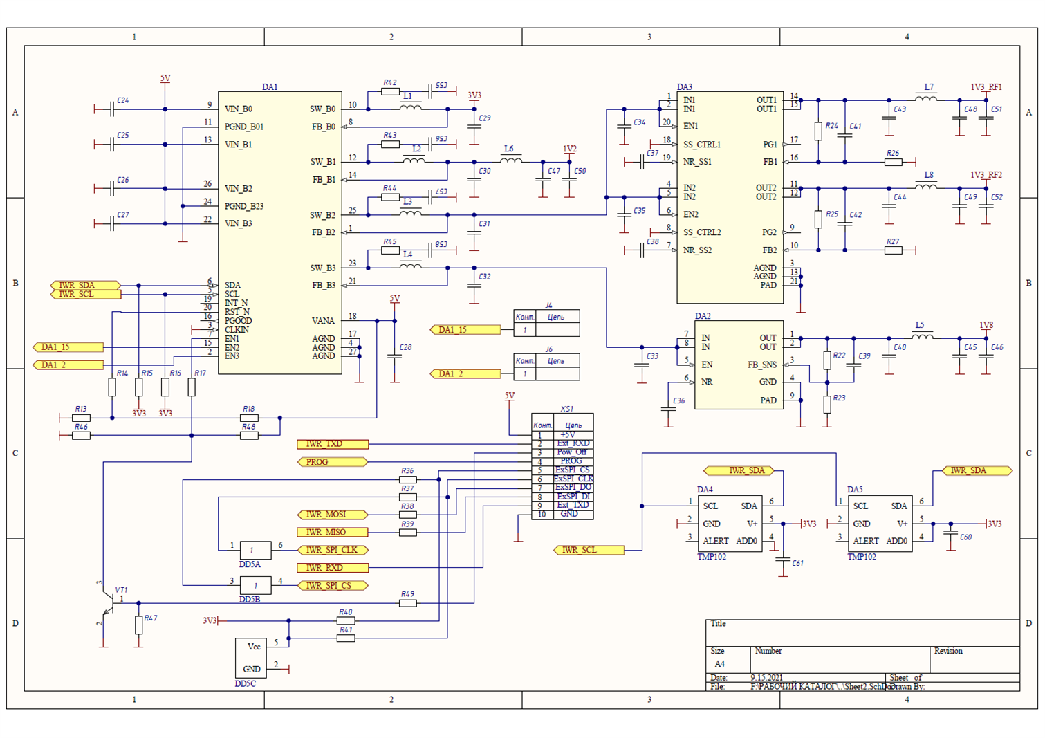
We use power supply schematic from IWR1443BOOST kit board. There are identical spurious spectral peaks in all RX channels caused by LP87524-Q1.
Those spurious peaks are 3-5 times above average noise level. The same are on the kit board .

Can you recommend any solution of the problem?

Regards,

Gennadii Lichkov

  • Hello,

    In what frequencies do you see the spurious peaks?

    Thanks.

    Regards,

    Tomi Koskela

  • Hello,

    Looks like in IWR1443BOOST EVM, with LDO Bypass option, there is single 22uF output capacitor on each regulator output before the 2nd stage 100nH inductor. To improve the stability and noise performance, we need atleast 2x22uF output capacitors on each rails. Can you please add additional output capacitors on each regulators and see whether this issue goes away? If the issue is still there, then more capacitors  (like 10uF or 22uF) should be added after those 100nH inductors, mainly on 1.8V and 1.0V rails.

    Regards,

    Murthy

  • Hello Tom, Krishnamurthy,

    Our power supply schematic is identical to IWR1443BOOST one. There are LDO. We tried wide range of inductors up to 330 nH and capacitors up to 47uF after LP87524-Q1 and further after LDO on 1.3V and 1.8V rails.

    Unfortunately it didn't help.
    Here are RF spectrum containing spectral peaks. There are no reflected signals there. Spurious spectral peaks are stationary in frequency and variable in amplitude. You can see them on IWR1443BOOST.

    Regards,
    Gennadii

  • Hello,

    Can you please reconfirm whether these spurs are indeed in KHz range (4KHz-10KHz) and not in MHz range? Switching regulators are switching at 4 MHz and low frequency noise should be filtered through LDO's. Also, AWR should have some HPF's and I am not sure whether these spurs are really related to PMIC. Changing the 470nH inductor to different values does not help much. You have to add additional LC filters after the main LC filter to reduce the regulator ripple. But if the issue is in few KHz range, this 2nd stage LC filter wont help much. Have you already tweaked LDO external components? Have you also tried to change your Chirp settings to see whether this spur frequency is changing with Chirp settings? It could be also possible that there will be some low frequency spurs related to load transient ringing issues.

    Regards,

    Murthy

  • Hello,

    We observe signal after mixer and IF chain. The spectral peaks can be results of MHz to kHz shift of PMIC spurs by the chain. We have already tried to reduce main LC filters cut-off frequency. It didn't help.
    Reducing of the chirp slope reduces spur frequencies. They occupies the same bins due to decrease of the deviation. The observed noise picture does not change.
    We turned on SPREAD_SPEC of PMIC. It leads to slight amplitude decrease and significant bandwidth increase of the spurs.

    Regards,

    Gennadii

  • Hello,

    Usually we see that if PMIC switching frequency is coupling, then in FFT also, we see it at 4 MHz. So, i didn't fully understand how this MHz to KHz shift can happen.

    * For regulator stability and noise point of view, we need minimum 2x22uF capacitors on the regulator outputs. Please add  them if you have single 22uF on each regulator output. Do not change 470nH main inductor value.

    * If the issue is related to PMIC switching frequency ripple, then adding 2nd stage LC filter before the LDO should normally help. LDO used may not have good PSRR at 4 MHz and it may not be able to filter the switching frequency ripple.

    * Usually with spread spectrum, PMIC switching frequency spur amplitude should reduce considerably and noise floor around switching frequency will increase a bit and this is normal.

    * If there is a layout related coupling which is causing this spur, then it should be fixed in the layout and adding additional filters may not help much.

    * Please send me your schematics diagram so that I can take a look at it.

    Regards,

    Murthy

  • Hello,

    Here are our schematics diagram.

    Regards,


  • Hello,

    Thanks. Since component values are not mentioned in the schematics, it is difficult to review the schematics against the recommended values. But see the below feedback from my side.

    * I assume that 470nH inductors are used and input capacitors are 10uF and output capacitors are 22uF.

    * 3.3V rail: It needs additional 22uF output capacitor in parallel to C29 for the improved stability. Also, at board level, there can be some coupling from 3.3V rail to RF area and 2nd stage LC filter (100nH inductor or ferrite bead + 10uF/22uF capacitor) is recommended on 3.3 V rail as well. Place this 2nd stage LC filter close to PMIC area to filter the noise as close as possible to the PMIC to minimize the noise coupling issues on the PCB.

    1.2V rail: It needs additional 22uF output capacitor in parallel to C30 for the improved stability. I assume that L6 is 100nH and capacitors after L6 are 10uF or 22uF. Also place L6 and those capacitors next to L6 close to the PMIC area to filter the noise as close as possible to the PMIC to minimize the noise coupling issues on the PCB.

    1.8V rail: I hope C34, C35 are 22uF capacitors. If these are small, then additional 22uF capacitor needs to be added in parallel to C31. Also i think it is better to place L7, C48, C51 (2nd stage LC) before the LDO input and place them close to the PMIC area to filter the noise as close as possible to the PMIC to minimize the noise coupling issues on the PCB. In this case, L8, C49, C52 may not be necessary. Also, I assume that LDO's have sufficient output capacitors.

    2.3V rail: I hope C33 is 22uF capacitor. If this capacitor is small, then additional 22uF capacitor needs to be added in parallel to C32. Also i think it is better to place L5, C45, C46 (2nd stage LC) before the LDO input and place them close to the PMIC area to filter the noise as close as possible to the PMIC to minimize the noise coupling issues on the PCB. Also, I assume that LDO's have sufficient output capacitors.

    In general, even with just the 2nd stage LC filter (without LDO's), we are able to achieve good performance and I think issue you are seeing is mostly some PCB related coupling and layout should be carefully looked.

    Regarding the issue you have seen on IWR1443 EVM, I have asked IWR apps team to check and I will get back to you once I have more information on this.

    Regards,

    Murthy

  • Hello,

    Here are components values

    Regards,

    Gennadii

    iwrparts.xls

  • Hello,

    I looked in the BOM and see the below additional feedbacks.

    PMIC input capacitors: They are 10uF capacitors in 0603 package and their capacitance may significantly degrade at 5V input and here our recommendation is to use 10V rated capacitors. If board temperature is expected to go beyond 85C, then X7 type capacitors may be needed.

    VANA capacitor: Please change it to 100nF from 220nF, but this is nothing to do with the spur issue you are observing.

    BUCK output capacitors: Capacitors close to LDO inputs are 10uF and hence you would need to add more capacitors on BUCK outputs to have at least 2x22uF.

    2nd stage LC filter capacitors: single 10uF and 1uF capacitors are used, difficult to say whether this is good enough.

    Regards,

    Murthy