This thread has been locked.

If you have a related question, please click the "Ask a related question" button in the top right corner. The newly created question will be automatically linked to this question.

FDC1004: Frequency in FDC1004 & FDC2214

Part Number: FDC1004
Other Parts Discussed in Thread: FDC2214

Hello,

I have a query regarding FDC1004 and FDC2214. Apologies if the question is too naive as I am still exploring the FDC1004 and FDC2214.

My aim is to get a frequency response. 

FDC1004

From the datasheet that I see that it operates @ 25 KHz. Is this fixed?

I read this statement in one of the technical documents.

".the FDC1004 supports fast mode frequencies 10 kHz to 400 kHz". Does this mean that this can be altered? If so, how? I am able to operate the FDC1004 using arduino as well. Is there any option to do this?
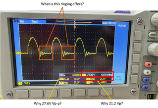
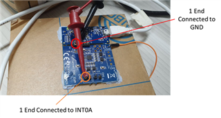
FDC2214

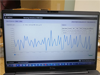
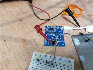
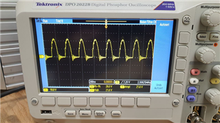
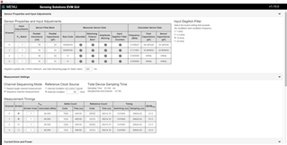
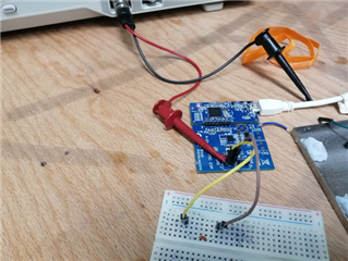
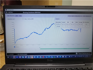
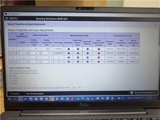
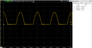
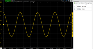
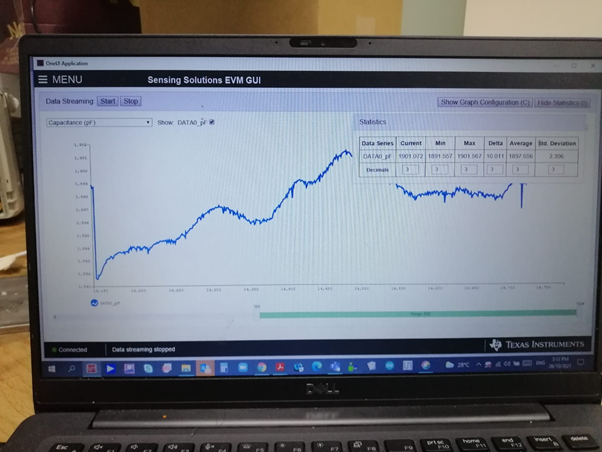
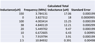
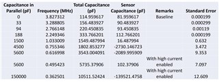
Connecting external   L and/or C, components across INA and INB, alters the resonant frequency. Below is a tabulation of my trials. I used the board capacitance and connected L&C in parallel for achieving frequencies >5 and < 5 MHz.

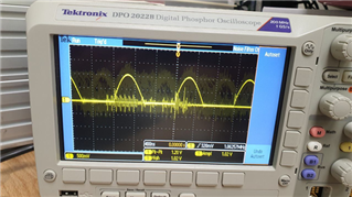
Anything below 1 MHz has a very high error. Am I missing anything here in terms of components, wiring, GUI options etc? Could you advise how to lower this noise? FDC1004 operates at 25 kHz and is not so noisy

Thanks

Hari

  • Hari,

    The FDC104 sensor frequency is fixed at 25kHz. 
    The reference to fast mode frequency refers to the I2C interface.

    The minimum recommended sensor voltage swing for reliable conversion is 1.2V. Your lower frequencies rely on larger capacitances, could result in resonant circuits which are harder to drive, so the device may be having problems achieving the 1.2V swing, even with the HIGH CURRENT option enabled.
    Please check the sensor voltage swings to see if this is the case, and let me know if this is, or isn't what is going on.

    Regards,
    John

  • Hi John,

    Sorry for the delayed response as I was away. I have attached some images below for reference as well. I tried to vary frequency by connecting external capacitor across iNA and INB

    1. With NO external capacitor  attached:

  • 3.. contd..

    When connecting a 2nF capacitor to drop the frequency to below 1 Mhz, we observed drifting in the FDC 2214. This is not desirable for sensing. The standard deviation was found to be quite high as well.

     I  connected an oscilloscope (1 end connected to INT0A and 1 end connected to GND) and the waveforms as shown earlier:

     The waveform was found to be very noisy and I am quite puzzled with the results I am looking at.


    I would like to ask:

    • Is this the right way to vary the frequency? If not, how should we actually be proceeding with this.? How to determine the 1.2 to 1.8 V swing? 
    • Why is the values drifting? if its input voltage related, what are ways to mitigate this?
    • Why the waveform measured on the oscilloscope is noisy? Any way to over come this.
    • We did connect the oscilloscope across INA and INB and never found voltages swing between 1.2  to 8. We tried changing all 31 setting on current detection as well but the moment we connect any external capacitor the drift and noise is high.

    Could u help us out.?

  • Hello Hari, 

    The frequency of the sensor is dependent on the L and C values of the sensor and any change in those will result in a change in the frequency. Additionally, when a target impacts a sensor, the frequency will also change since the sensed capacitance is changing.

    For the drifting value, there could be a couple different things involved. As the sensor oscillates it can heat up. It is best to use a C0G/NP0 grade capacitor to minimize the impact of this. Also, if you changed the inductor on the board, you can make sure that it is also relatively temperature stable to reduce any temperature impacts. Another possible issue would be the voltage rating on the capacitor. I doubt this is the case since the voltage is so low but you could have some issues if the capacitor is saturating at the top of it's voltage rating. Lastly for this would be to increase the current drive of the sensor (while still keeping it below 1.8V) and seeing if the issue is still present.  

    Your last oscilloscope measurement looks like it has multiple captures on it or persistence enabled. This might be holding onto some of the ringing in between the driven portion of the wave. Can you take the capture again without the multiple waves? Also, can you take a differential measurement (INB on channel2 of the scope)? 

    Thank you, 

    Justin Beigel

  • Hi Justin,

    Thanks for the response. I wish to clarify some points:

    -No external inductor was used.

    - No changes were made to L and C of the EVM

    -Only one channel of EVM was used for measurements (ch0). Muli-channel measurements were disabled. Both InA and INB separately were analyzed

    - No external sensor was connected to the EVM and the comparison is purely based on the pins of EVM (ch0- INA/INB)

    I would like to get some clarity on how to measure the voltage swing? What is 1.2 V to 1.8 V swing? What two terminals of channel 0 do we connect to an oscilloscope to see this?

    1. Under my query 1, NO external capacitor was attached (open circuit in breadboard)

    -sensor freq is 5 MhZ. EVM capacitance signal is stable with NO noise or drift .

    -However, I do not see the recommended swing (1.2-1.8V) when INA  in ch0 of EVM  was connected to channel 1 of the oscilloscope.

    2. Under my query 2, 2 nF external capacitor was attached to modify the tank frequency to 0.8 MHZ (closed-circuit in breadboard)

    -sensor freq is changed to 0.8 MhZ. EVM capacitance signal is DRIFTING continuously.

    -However, I do not see the recommended swing (1.2-1.8V) when INA  in ch0 of EVM  was connected to channel 1 of the oscilloscope.

    - We did try to connect the INA to channel 1 and INB to channel 2 of oscilloscope. We got opposite rectrified waves, which I belive is correct. But again, we do not see this 1.2 to 1.8 V swing.

    -several different values of L and C were connected in parallel to EVM LC tank circuit. We were able to change the resonant frequency successfully but not able to control drift.

    We are kind of lost here. Could you help us out?

  • Hello, 

    The 1.2-1.8V is the peak sensor voltage. You should see it on each side of the channel (A and B). Your image of the 2nF capacitor looks to be slightly too low for this. 

    I replicated the 2nF setup and took the following: 

    You can see the slight ringing on the waveform but when looking at it differentially, the ringing disappears: 

    You should be able to see a change in the voltage each time you change the Idrive code column in the GUI. If you aren't seeing an impact, can you go to the register page of the GUI and confirm that the setting is actually changing? 

    For the drift, what is the voltage rating of the capacitor and what type of capacitor are you using? Also, what different values have you used? Can you try using one that is only a few pF? 

    Thank you, 

    Justin Beigel

  • Hi Justin,

    Really appreciate your clarifications. It is helping us debug in a better way.  Slight smile Slight smile

    For the FDC,

    1. We did try changing the I drive setting for all possible settings (35).  We observed a decreasing amplitude of the waves with a reduced Idrive number. However, when we tried to use the "Idrive detect" option to check  (with power mode enabled) the rough current value, we noticed that it was "NaN". We are not sure why this happens. Not sure why the drifting persists.

    2. When operated in a differential mode the ringing is less and we got a full sine wave, but the amplitude was still high with the capacitor connected across INA and INB.

    3. The voltage rating of the capacitors is 50 V (through-hole). we varied the frequency down to 25 kHz using different capacitors. Anything other than default 5 MHz of EVM shows a drift.  For e.g., drift shown below:

    Any suggestions?

  • Hello, 

    I am not sure why the Idrive detect didn't work for you but that is just to get a recommended setting value within the voltage range of the sensor. Setting the value manually is fine. 

    The max capacitance measured on your graph seems less than the 2nF capacitor. Was this the case will all capacitors you tested? Even with drift, were they always below the expected value? 

    Also, in your original post, you mentioned the FDC1004 and FDC2214. Have you seen the following FAQs that compare the two: 

    Are you using both or comparing them for you application? 

    Best Regards, 

    Justin Beigel

  • Hi Justin,

    Sorry for the delayed response. Thanks for the mail and detailed answers so far. It has been indeed very insightful.

    Personally, I am a big fan of TI products and have been exploring both FDC2214 and FDC1004 to understand better for research applications.

    So far FDC1004 has been excellent but is severely restricted by the frequency range. I require an evaluation board with a frequency selection option and found FDC2214 to be the best option available. 

     For example, I wish to tune from 10 kHz to 10 MHz to observe the frequency response of the material under test.

    (10 kHz, 25 kHz, 50 kHz, 75kHz, 100 kHz, 250 kHz, 500 kHz, 750 kHz, 1 MHz, 2.5 MHz, 5 MHz, 7.5 MHz and 10 MHz.) 

    We noticed that a very small pF of capacitance is still ok w.r.t to noise/drift but that does not allow us to change the frequency much. We have so far tried the following

    -different capacitors and inductors

    -current drive option (35 options to fine-tune the oscillation amplitude)

    -ground shifting correction (notes in TI)

    -single and parallel data acquisition

    -different channels

    -with  and without parallel plates attached

    we noticed that the moment any external L or C is connected then the EVM loses its excellent SNR with the default frequency (5 Mhz).

    Do you think surface-mounted capacitors/inductors fabricated on PCB board is a better option?

    Are we missing something?

    Thanks

    Hari

  • Hello Hari, 

    In regards to the surface mounted components, generally, they perform better and with less noise but I wouldn't expect this much of an issue with a through-hole component so there may still be something else going on. 

    The FDC2214 isn't really designed to operate over a wide range range of frequencies. It works best when you design for it to work around a set frequency. The Optimizing L Measurement Resolution for the LDC161x and LDC1101 app note is targeted at our LDC devices but some of the same concepts can be applied to the FDC2214 and how the resolution is impacted by different design changes. Having the FDC change from 10kHz to 10MHz is a large shift and to get best resolution, you would need to optimize at each individual step. 

    Best, 

    Justin Beigel

  • Hi Justin,

    Thanks for your inputs. Sorry for the delay as I was unable to access oscilloscope during WFH. As per your suggestions, I got some plots for your feedback,

    I have tried to reduce Idrive to its lowest setting to try to get the voltage to be in the 1.2V-1.8V range for the FDC2214 with nothing connected.

    However, with the lowest Idrive setting, I was only able to bring the voltage down to 21.2Vp and 27.6Vp-p. I have also observed some ringing effect in the waveform.

    One end of the oscilloscope is connected to GND and the other to INT0A.

    I have also tried disconnecting one end of the oscilloscope from GND but the volatage still is not in the 1.2V-1.8V range.

    I would like to ask:

    1. Why is the Vpeak-peak 27.6V?
    2. Why is the Vpeak 21.2V?
    3. What is causing the ringing effect
    4. Is it possible for you to show how the oscilloscope should be connected with a picture so I can check if the way I measure is correct?

    Oscilloscope observation shown here:


    1. Please also advise on whether the connection shown below here is correct:

    Even without any external L or C, the 1.2 to 1.8 V is not achieved but the EVM operates very well at 5 MHz.

    Kindly let me know what you think.

    Thanks

    Hari

  • Hello Hari, 

    The peak voltage issue looks like it might be an oscilloscope setting. The FDC cannot output that high of a voltage so there may be a setting on the oscilloscope somewhere that is acting as a gain. Possible a 10x setting on a probe? 

    The ringing effect is a product of looking at half of the sinusoidal waveform. You can look at the differential output and the ringing will go away. However, some oscilloscopes will internally connect the GND of the probe so you may need a dedicated differential probe to look at the differential output of the device. The single ended capture I took above even had some ringing but it may be less due to the different capacitance impact between the different oscilloscope probes. 

    They way you are measuring the peak voltage/amplitude is correct with the probe connection. I wouldn't worry too much about the ringing for now and focus on the voltage level of the measurement. 

    Best Regards, 

    Justin Beigel