This thread has been locked.

If you have a related question, please click the "Ask a related question" button in the top right corner. The newly created question will be automatically linked to this question.

FDC1004: Sensing current and conversion to DC output from FDC1004 and FDC2214

Part Number: FDC1004
Other Parts Discussed in Thread: FDC2214

Hello,

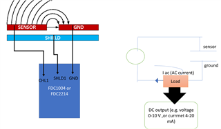
If i use a two-electrode sensor and connect to FDC1004 or FDC2214, I am able to get the capacitance readings. I have represented it by the diagram below

 I have the following questions:

1.How to detect AC current if the circuit representation for the schematic is as above (right)? What range are we talking about for 1-15 pF? pA or nA?

2.Is it possible to sense the AC current (Iac) in the circuit? Does TI have an amplifier/current sensor that can detect FDC1004 or FDC2214 AC current levels?Any resistor load is required?

3.How to covert the Iac to DC output (voltage or current)? Does TI have any AC current to Analog DC output convertors?

The idea is to build something similar to commercial capacitive proximity sensor where the output is DC 4-20 mA or 0-10 V.  Apologies for the naive questions as I am not an expert in this field.

Thanks

HAri

  • Hari,

    You have a few options for estimating the AC current.

    1. The first option is to carefully characterize the sensor and understand the reactance, and the equivalent parallel resistance (Rp).
    You can then calculate the sensor current by diving the Rp into the measured sensor voltage. 

    2. The second option would be to use one of our current monitoring devices - usually with an INA prefix - with a small in-line resistance to measure the sensor current.

    Both approaches have advantages and disadvantages.

    Option 1 will require the sensor to be characterized over the application's temperature range. Also, the sensor will have to be re-characterized whenever a change is made.
     It may or may not require a gain/buffer amp to help measure the sensor voltage. 

    Option 2 requires the addition of the current shunt monitor and the supporting sense resistor. Its advantage is that current is actually measured, and it will work over temp-based sensor changes, or over sensor re-designs. The only disadvantage is additional parts, which may be on par with Option 1, if a buffer/gain amp is needed.

    You can convert the AC voltage/current to a DC voltage using something as simple as half-wave or full-wave rectifiers followed by some filtering and gain.
    There are many options available, and a good place to start is our design resources page for amplifier circuits.

    Also, if you would like more info on FDC devices, there are some FAQ pages for the FDC1004 and the FDC2x1x devices.
    The FAQ pages contain descriptions and links to app notes and blogs for those devices.

    Regards,
    John