This thread has been locked.

If you have a related question, please click the "Ask a related question" button in the top right corner. The newly created question will be automatically linked to this question.

BOOSTXL-TUSS4470: Where to source a transformer for the eval kit

Part Number: BOOSTXL-TUSS4470
Other Parts Discussed in Thread: BOOSTXL-TUSS4440, TUSS4440, TUSS4470, PGA460

Hi there,

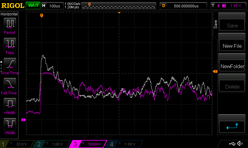
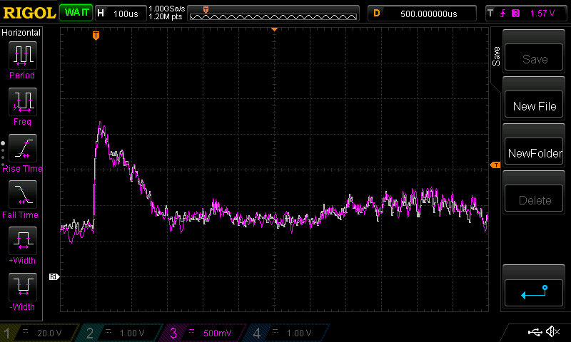
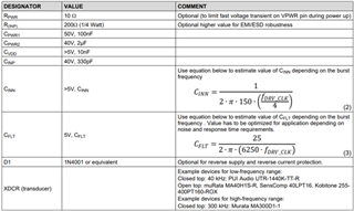
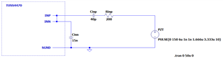
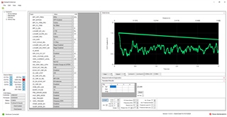
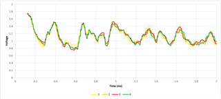
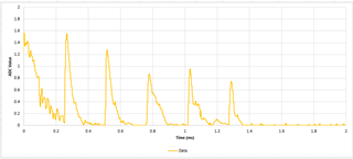
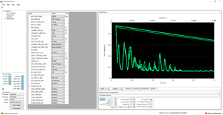
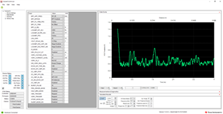
I've been doing some tests with the BOOSTXL-TUSS4470 on my application and I'm finding that I'm just not getting any TOF back. The application is a steel container and I'm trying to measure the water level. I'm using a 1MHz PZT and using only mono static and setting VDRV to 20V.

I was looking to attach a centre tapped transformer to trial the transformer drive mode and increase the drive voltage substantially but the coilcraft WA8351-AL in the designs BOM is out of stock and I'm eager to get trial it out. Do you know where I can source something similar? The only alternatives I can see on the market are stated for around 50kHz and not the much higher 1MHz (though I could reduce this). Or would you say I have to get the BOOSTXL-TUSS4440 instead and use this? I'm thinking if the difference is just the transformer it's difficult to warren the £185 for the BOOSTXL-TUSS4440 when I have the 4470 one.

Thank you in advance

  • Hi Louis,

    The E2E thread linked below includes a table for alternative transformers.

    https://e2e.ti.com/support/sensors-group/sensors/f/sensors-forum/620399/pga460-air-coupled-ultrasonic-transducers-transformers-listing


    I have never tried to use a transformer with the TUSS4470, but you are correct, it should be possible as the BOOSTXL 44x0 EVMs use the same PCB. Note, the TUSS4470 uses an H bridge output stage, and the TUSS4440 uses a stronger half bridge driver output stage. Additionally, it will likely be necessary to use a transducer with a lower frequency due to the use of a transformer.

    I am always happy to look over the 1MHz TOF measurements to understand why there is no TOF return signal.

    Please let me know if you have any questions.

    Thank you,

    Jacob

  • Hi Jacob,

    Thank you for the offer.

    Below are 2 examples of the signals I'm receiving. Both the pink and white traces are averaged over 8 samples to remove noise during development. The white trace is the first setup and the pink trace is the second. I found that I would get quite different signals when disconnecting and reconnecting the PZT even though everything is the same. The connections from the dev board and the PZT all seem fine. I'm coupling the PZT onto the container using super glue following the BOOSTXL-TUSS4470 user guide (though my super glue didn't have latex).

    Calculated TOF should be 85-105uS

    The TOF echo would likely be hidden here. On the white trace it looks like a bump at ~265us when there shouldn't be.

    Calculated TOF should be 340-325uS

    There is no TOF echo here, unless it's the little bump at 350us but it's so small that it would be hard to reliably detect in my opinion especially as the bump shape is similar to the previous capture's~265us bump.

    Compared to a plastic container

    I have received very good results using a plastic container but when moving to a steel one things get a lot worse. I've discovered that the impedance mismatch between water and plastic and water and steel are significant.

    Using the formulas in the Ultrasonic Sensing Basics report, with a signal going from steel to water, water reflecting from air and then water to steel again (not including the losses from the 2 super glue to steel transitions) I would get back 1.39% of my original signal whereas the same thing with a plastic container (with acoustic impedance of 2.4) and I would get back 87.16%. Bear in mind I'm using the direct drive configuration so I'm only outputting 20V pk-pk. 

    Overall project

    The overall project needs to be able to measure the TOF of a container which would be a maximum of 50L and a max height of almost 1 metre. I would also like to be able to detect down to a TOF of maybe 80-100us. 

    What are you're thoughts?

  • Hi Louis,

    Thanks for the detailed information here. 

    I agree, there does not seem to exist a measurable echo in the scope shots. I also agree the small bump in the ~330us TOF is too small to measure in a  repeatable way, especially being that it is so similar to the ~100us TOF.

    The difference between steel and plastic make sense. The Ultrasonic Sensing Basics report gives a good reasoning for why may not be observing a return echo. Thank you for calculating the return signal strength for the plastic and the steel, I would consider this to be the primary cause for the difference.

    The most reasonable and effective way to improve the return echo would be via increasing the SPL of the transmit wave or increasing the sensitivity of the receiver. For a TUSS44x0 device we could use a transformer to excite the transducer with a higher voltage. Note, some transducers have max drive voltages too low for use with a transformer. It is recommended to consult the datasheet to help understand if the transducer is capable of use with a specific drive voltage and or burst count.

    Burst count can also increase to improve the SPL of the transmit wave, however you will lose short range sensing distance in a monostatic configuration.

    Finally, increasing the gain for the device can help with improving the relative strength of the echo. Assuming the device gain isn’t already maxed out for the LNA, you can increase the LNA gain and alter the log amp to improve the dynamic range of the receiver.


    I have seen other applications have success with using a transformer to increase the amplitude of the return echo. It is unfortunately difficult to estimate the effectiveness without conducting real world tests.


    I am happy to answer any questions you may have.

    Thank you,

    Jacob

  • Hi Jacob,

    I am trying to test out a transformer using the BOOSTXL-TUSS4470 (not the BOOSTXL-TUSS4440 which would be preferred because it's already setup but they are quite expensive). I've added a 300kHz transformer and transducer (200V pk-pk max). At this time I've removed the transducer signal from INP by removing R12 because I was concerned about the increased voltage seen at the INP pin. 

    Looking at the PZT signal only it looks to be fairly good when using the boards pre-driver and setting the config setting. So I'm looking to start testing on an actual steel container ASAP. But first I want to ensure I take the required precautions. Could you also answer the questions below please?

    1. I'm assuming I need to calculate the max voltage at the TUSS4470 INP pin and adjust C9 and R11 accordingly?
    2. Also, I couldn't see anywhere which describes how to calculate mono-static receiver components C10 and R13. I'm assuming they are for dampening but not sure how to calculate their effectiveness unless it's trial and error?
  • Hi Louis,

    Great to hear the preliminary tests are looking promising for the performance.

    1. You are correct, I recommend verifying the INP pin is not being overdriven after the addition of the transformer. Values for C9(CINP) R11(RINP) can affect the voltage that appears at the RINP pin. The datasheet recommendations are usually optimized for general use, but it doesn’t hurt to verify everything is within specification, especially if the transformer is different compared to what was used in the EVM.
    2. The receiver components C10 and R13 can be very critical to transducer performance. Unfortunately, there is no easy way to obtain exact values without some amount of trial and error. Section 4.4 of SLAA732 details the process for tuning the capacitor and resistor in a monostatic transformer driven application, Link here: SLAA732. Note the document is catered to the PGA460 device, but the ideas regarding tuning will be similar among any ultrasonic AFE that uses a transformer. A rough range for tuning capacitors is usually from 100pF to 2000pF, and Rdamp from about 500ohm to 25kohm.

    Please let me know if you have any questions. I am looking forward to seeing the results of the test with the steel container.

    Thank you,

    Jacob

  • Hi Jacob,

    Thank you for your response.

    On point 1. I'm still not sure how to calculate the values for Cinp and Rinp. The BOOSTXL-TUSS4470 (same as BOOSTXL-TUSS4440) has Cinp as 330pF and Rinp as 200r. The voltage applied from direct drive could be effectively +/-20V whereas if I use a transformer it would be larger in almost every case. In my case I'm expecting effectively +/- 150V. My transformer is 1:1:9 and the BOOSTXL-TUSS4440 board is 1:1:8.4 so very close (the BOOSTXL's transformer is out of stock). I can see from the TUSS4470 datasheet that it must be less than 0.5V always.

    Should I use Rinp, Cinp and Cinn as components in a potential divider to calculate the voltage at the INP pin at a given transformer output voltage at a given frequency? See the LTSpice sim image below. 

    The voltage at the INP pin would then be

    Vinp = Vtransducer * ( Zcinn / ( Zcinn + Zcinp Rinp ) )

    For Vtransducer = 20V, frequency = 300kHz and the components as fitted and Cinn selected to be 15nF I'm calculating 0.38V. If being driven by a transformer, Vtransducer could be say 150V and so I'd calculate to be 2.88V. I calculate that if I changed Cinp to 40pF, Vinp would be 0.39V so pretty close. I might be wrong to consider Cinp, Rinp and Cinn in this way though. 

    On point 2. Thanks for this, I start somewhere and tune to the best position with C10 and R13.

    Thanks again,

    Louis

  • Hey Louis, 

    I verified with another Engineer that the DC blocking cap(CinP) and series resistor(RinP) suggested in the datasheet will be suitable to prevent damage to the INP pin with a similar transformer to the EVM. I was unable to find the max .5V spec, but I was able to find that mentioned as an abs min specification for INP.

    The 1.3V abs max voltage also made me question if the current setup would offer enough protection to the input. I do not have a TUSS4440EVM with me in lab, so I am unable to measure the voltage induced on the INP pin upon bursting with a transformer. You are welcome to alter the values to ensure there is no chance for damage during testing. The TUSS4440 datasheet mentions the use of a 3kohm resistor in place of RinP for typical applications. I recommend starting with a value like that for testing purposes. This should help limit the current charging the DC blocking cap. I have used the TUSS4440 EVMs in the past, and never had issues with damaging the INP pin. You are also welcome to alter the capacitor to ensure INP is not damaged during bursting. 

    The other Engineer also commented that he had never seen the TUSS4470 used with a transformer before. I agree the cost of the EVM may not warrant a change to a very similar product. An alternative may be to pursue purchasing a single TUSS4440 and solder it in place of the TUS4470. the EVM PCBs are shared between the two devices, so there should be no complications there. 

    Final point, I would recommend progressively working towards the higher drive voltages. At a certain point, transducers do not generate more SPL versus drive voltage. I would also monitor the INP pin just to verify everything is within specification. I realize the reference design for the TUSS4440 uses a drive voltage of 70V after the transformer whereas you would like to go higher. I just want to make sure we don’t unintentionally damage the device.

    Please let me know if you have any questions,

    Thank you

    Jacob

  • Hi Jacob,

    Ah OK. I read the maximum value for VINx to be from 0.5-1.3V and so I'd need to make sure it's below that range and therefore 0.5V max. The TUSS4440 has the same requirements as the TUSS4470 on the VINx pin and is the same on both BOOSTXL circuits. So to my mind the TUSS4470 can do the same as the TUSS4440 in terms of driving a transformer as long as the TUSS4470 uses the pre-driver mode (and external pre-driver components already fitted on the board). And as the TUSS4440 is connected to a transformer by default it must see higher voltages so unless it's different in the input tolerance sense I don't understand why the TUSS4470 would be different.

    I'll connect the transducer signal to the TUSS4470 via the RCinp components and see what I get. I'll ramp the drive voltage slowly to see what I get on the output. If I don't see what I'd be expecting I may need to order the TUSS4440 EVM but to be honest I don't really understand the differences considering the pre-driver stuff above. 

    Thank you,

    Louis

  • Hey Louis, 

    You are correct on the specs for the TUSS44x0 parts being the same specification for input voltage on VINx. This makes me feel a bit better about the receive circuitry being able to tolerate the higher voltages from the transformer for the TUSS4470.  

    I am always happy to look over the results of the testing. As for your comments on the pre-driver mode driving external components, you are also correct. That would be a configuration that would essentially make the parts very similar from a functional device standpoint. 

    Thank you,

    Jacob 

  • Hi Jacob,

    I've got everything setup for the plastic container using the transformer approach. Below is the circuit I'm trialling on the BOOSTXL-TUSS4470 and the TUSS Generation III EVM GUI configuration I'm using. I've highlighted the connections being used.

    Xformer attempt

    The transformer is Epcos part B78416A2360A003 (300kHz 1:1:9) with secondary inductance of 3mH. The Transducer is Multicomp part MCUSD13A300B09RS (300kHz). C6 is fitted with a 100uF 35V al cap. Note that the BOOSTXL-TUSS4440 is fitted with a Coilcraft WA8351-AL which is very similar to the Epcos part in turns ratio and secondary inductance. VPWR was set from 7.5V to 10V for trials which gave around 157-183V which connected to a scope but I know that effects the PZT signal. Also note that I've not yet fitted C10 which I know will effect the resonance of the circuit from your guide here. I'll try this today but I'm not feeling too hopefully it'll change everything as much as needed.

    Here are the results I'm getting from the TUSS Generation III EVM GUI which are terrible. I tried a whole variety of config settings to get as best a signal as I could but I'm open to suggestions.

    Plastic Container Data (HV 300kHz XFMR + PZT).xlsx

    In comparison, using the direct drive approach (no transformer) on a plastic container and a 1Mhz transducer yields incredibly good, clean results. I understand that the change in transducer frequency will change the peak shapes but the signal itself is very different. Note that the fluid heights are different so different TOF's will be expected.

    Plastic Container Data (1MHz Direct Drive + PZT).xlsx

    I was expecting it would look the same except for wider peaks but it's quite different. I'm looking get this to work and then I'll move to the steel container for trials. 

    Is there anything that you can think of?

    Thank you, Louis

  • Hey Louis,


    I am sorry to see the results are so poor with the TF drive. In my opinion I do not see much of a return signal in the GUI, unless you expect the return at around .65ms


    Below are some of my initial recommendations to possibly improve the echo.

    You can use a BPF instead of the HPF. I do not think this is the reason for issue, but it could reduce any HF noise that may couple into the input.

    On the topic of noise reduction, you can also try to adjust CFLT. I am uncertain what value you are currently using, but I roughly calculated around 2.2 nF as a value for 300kHz drive frequency (this does not have to be an exact value).

    C10 will make a difference, but I am hesitant to say it will be the drastic change required for the desired improvements. 

    It may be helpful to scope the transducer to verify the burst looks proper, and that the ring down of the transducer is sufficient for the application. If the ring down of the transducer is taking too long to decay, it is possible that the return echo amplitude will be affected.


    Hardware wise, the transformer and pre-driver look proper. The register settings do not appear to have any issues at a quick glance.

    One note in looking at your Excel results, the echo signal results look reasonably consistent even though they do not possess a prominent return echo like the direct drive. This makes me believe the waveform is representative of the sound waves, as noise would likely cause the results to look reasonably different between tests. 

    I can consult with the team regarding any further suggestions they may have. Assuming the transducer was excited at the mentioned voltage level, I would expect to see a pretty clear echo relative to the noise of the system. This is a reason why I think verifying the burst signal may give some insight into what is occurring. You could also probe transformer inputs to verify the FETs are switching properly.

    Thank you,

    Jacob

  • Hi Jacob,

    Thank you for your response. I added Cdamp as 3.9nF and found that it did fix the issue with the plastic container. I was then seeing good results. My setup was using 7V drive from the TUSS4470, 7.5V at VPWR. 

    So I then moved back to the metal keg and was receiving bad results again. I changed CFLT to be effectively 1.68nF (by using C1 and C2) as suggested but this didn't change much. I also changed the VDRV and VPWR to 10V. I scoped the transducer lines and saw about 100V pk-pk. I did note that I didn't see more than this is when raising VPWR to to 15V. I'm wondering if the transformer isn't delivering enough drive current? Below is a screenshot of the steel container, note that the peaks should be around around ~300-350uS. You can see it's not great, there are 2 peaks which look good but I don't understand why they would be there and not before, I've certainly not got 0.7mS worth of water in the container!

    After scoping the PZT line, I'm quite sure the MOSFET's are triggering correctly because the transitions are sharp.

    Thank you,

    Louis

  • Hey Louis, 

    Great to see the improvement of Cdamp, the plastic tank looks great. 

    It is possible the transformer is limiting the current delivered to the transducer for the higher VPWR settings. 

    It is interesting to see the prominent spikes with the keg appearing at unexpected points. Sometimes the geometry of the tank can affect the TOF response. For example, in some cases the tank walls can reflect the signal back at a different time than the calculated ideal TOF. An easy way to test this is to change the water level to different points, both higher and lower than the current setup. This will help us understand why the TOF looks the way it does, and possibly what is causing the TOF to be incorrect. 

    Please let me know if this testing is possible, I am very interested to see if the results will correlate with changes in water level.

    Thank you,

    Jacob