This thread has been locked.

If you have a related question, please click the "Ask a related question" button in the top right corner. The newly created question will be automatically linked to this question.

DRV5053-Q1: Variability between sensors

Part Number: DRV5053-Q1
Other Parts Discussed in Thread: DRV5053, DRV5056, DRV5055

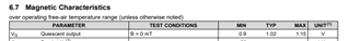
I have been using the DRV5053 hall effect sensors to measure the change in magnetic field of a permanent magnet. I am using several sensors at once and the problem I am having is that the sensors are not very consistent with each other. I am seeing up to a 60mV difference between sensors when not in a magnetic field. I get similar results when I subject all the sensors to the same magnetic field. I am looking for a change of around 100mV (a little over 1mT since 90mV/mT for this sensor) as a trigger so 60mV is very significant. I should add that I am filtering the power and signal as recommended by the data sheet.


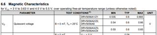
I have ordered some DRV5056 sensors for more resolution since I only need to measure in one direction. I have seen on your forums that they have a higher accuracy. The data sheet shows a lower noise level than the DRV5053. I am also looking into adding in a low pass filter to shorten the range to reduce the noise as recommended by the data sheet. In addition to these improvements, is there any kind of calibration sequence that is recommended for these type of sensors? Or any other way to improve accuracy over a small range? Are there other sensors I should be using instead?


Please let me know if  I am on the right track.

  • Matthew,

    Thanks for reaching out with your question.  The quiescent output voltage for DRV5053 is listed as shown here:

    So your variation of 60 mV is within the typical spec for this device.

    For DRV5056, the range is tighter:

    One thing to be mindful of with DRV5056 is that this sensor is only sensitive to a single pole.  You'll notice the the quiescent voltage of DRV5053 was mid range, where for DRV056 it is at the minimum range.  You'll want to be mindful that the magnet is always installed to produce a positive input to the device. When the opposite pole is presented then the device will have no measurable output.  If you need a response to both magnet poles then I'd recommend you take a look at DRV5055.

    Both devices should be fine with some output filtering, and in a trigger application I wouldn't anticipate that you'd need a high operating bandwidth on the output.  

    To reach optimal performance it would be best to utilize some sort of calibration. This could be an offset correction without the magnet or even a sensitivity correction to account for device to device variation on installation and gain.  A simple calibration routine would be to place the magnet at targeted locations.  If you are setting up a linear track of sensors, I'd recommend spacing the sensors with a slight overlap of their linear output region.  Then, for calibration I'd position the magnet at the edge of each linear region.  This should give you a max and min value for each sensor that you can use to match the output slope to the mechanical position for each sensor.

    Thanks,

    Scott