This thread has been locked.

If you have a related question, please click the "Ask a related question" button in the top right corner. The newly created question will be automatically linked to this question.

TDC1000: Hardware configuration for TDC1000

Part Number: TDC1000
Other Parts Discussed in Thread: TUSS4470

Hi,

I'm getting started with TDC1000 and I want to integrate it on my proximity sensor application. I want to make my own PCB with my own controller.

My goal is to detect distance of an object in the range 0 - 4m without a defined strictly accuracy.

Since I'm a firmware engineer I'm very confident with firmware side but not very confident of the hardware side.

I had a look at the TDC-1000 Eval board and at the schematic. Like I said, I'm understanding the logical connection, but I'm wondering if this application is compatible and suits my needings(?)

In particoular, these are my requests:

- Schematic of EVAL should work in my case? 

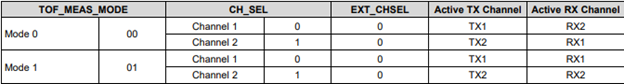
- What mode should I program through SPI? Since mode 0 is for level and fluids and mode 2 is for water flow metering, I guess the mode 1 should work for proximity but I'm not sure because is not specified.

- In the para 9 of datasheet there are several applications, but not the proximity so I can't compare the pictures. By the way, the proximity is stated at the beginnig of the document so I think the TDC1000 is compatible.

- How to set the PGAGAIN and LNAGAIN? Are them required? Do they require a particoular driver-circuit? In the EVAL module is left unconnected.

Are there any application notes or reference schematic to follow?

Thanks and regards,

Marco.

  • Hi Marco,

    Thank you for your question,

    For ease of implementation, we typically recommend users use the TUSS4470 device for direct drive ultrasonic systems up to 1MHz. The TUSS4470 is easier to design with, and most settings are configured via device registers as opposed to some of the characteristics for the TDC1000 requiring hardware tuning.

    That being said, the TDC1000 will be capable of time of flight measurements for proximity sensing.

    Have you selected a transducer frequency for the application yet? Additionally, will the application be sensing distance in a fluid based medium?


    The schematic for the TDC1000-C2000EVM should work in your case, but some of the filter components may be subject to change depending on your transducer frequency.

    Either mode-0 or mode-1 will work for proximity sensing. The selection between mode 0 and 1 primarily configures the Rx and Tx pair for the ultrasonic sensing.

    The TDC1000 was designed more for fluid level sensing/ flow metering, but proximity sensing can be implemented via a TOF measurement. Note, the transducer field of view and the size of the target may influence the accuracy for the proximity detection.

    The LNA gain is set to 20dB from the passive selection in the feedback of the amplifier. The PGA is programmable via device register from 0dB up to 21dB. Section 8.3 of the TDC1000 datasheet details the device signal path in more detail.

    I am including some helpful reference material below, but you can follow the datasheet recommendations for hardware implementation/develop from the EVM design.

    TDC1000-C2000 User’s guide

    Ultrasonic Sensing Basics


    Please let me know if you have any questions on the TDC1000 of the TUSS4470,

    Thank you,

    Jacob

  • Hi Jacob,

    thanks for the answer. I prefear the TDC1000 because has 2 inputs and I need both. (selected form the SEL pin from MCU to TDC1000).

    Regarding the transuducer, I have this one https://www.mouser.it/ProductDetail/CUI-Devices/CUSA-TR80-15-2000-TH?qs=HBWAp0VN4RjpgoemVHhFOA== 

    working @39KHz.

    Are all your considerations still valid?

    I'll read the document provided but have you also a note explaining the principle of tuning the filter components?

    Thanks again,

    Marco.

  • Hi Marco,


    Thank you for detailing the application a bit more.


    In the case of 39kHz, I would not recommend the TDC1000. The datasheet specifies operation down to 32.5kHz, but the problem becomes the ability for the TDC1000 to sense the return echo. It is possible to add external gain to the TDC1000, but ultimately, it becomes far more challenging to use the TDC1000 at low frequencies than alternative solutions with multiple devices. There is no specific document on modifying the filter components other than the DS.

    Can you detail the reason for the two-transducer input setup? Are you trying to sense a wide FOV?


    Thank you,

    Jacob

  • Hi Jacob,

    in my application I would cover a wide range of beam. So with 2 transducers positioned differently I can achieve it.

    Secondly, 2xTUSS470 will become more expensive.

    An other idea that came in mind is that with a switch driven by firmware I can deviate the signals to the transducer that I want to use on my measure (having only one channel). 

    Can the trick do the job in your opinion?

    Thanks,

    Marco.

  • Hi Marco,

    That is a suitable way to accomplish the task. You can use a MUX or a switching circuit to distribute the signal to different transducer channels. Note, the MUX or switch will need to be rated for the voltage and current requirement for the application. 

    Regards,

    Jacob