This thread has been locked.

If you have a related question, please click the "Ask a related question" button in the top right corner. The newly created question will be automatically linked to this question.

BOOSTXL-TUSS4470: Requirements of Rdamp on the transducer line

Part Number: BOOSTXL-TUSS4470
Other Parts Discussed in Thread: TUSS4440

Hi TI,

I've been speaking to you on a few threads but thought it best to start a new one for clarity of what I'm now asking.

I seem to have progressed substantially and I don't really understand why. I have the BOOSTXL-TUSS4470 setup for driving a 1:1:9 transformer with the pre-driver FETs. I'm driving a 1MHz transducer from a supply of 7.5V and I think this ends up (because of current strength) hitting the transducer at around 100-120V (7.5 x 9 x 2 should be the max).I've set Cdamp and bulk decoupling cap for the transformer connection as per dev schematic. 

I am trying to measure water in a steel container and until this point I've been unsuccessful and I think this is for 2 reasons.

  1. is that the transducer is not facing the top of the water level and so the ultrasound waves are bouncing all over the place before getting back to the transducer. I've proven this is the case by testing on a flat portion of the container which works great. So I'm working on ways to resolve this and have some bits coming in to do that.
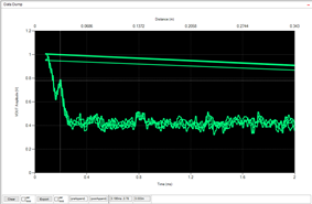
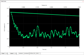
  2. Rdamp was set too high. I've been using resistances of 75-5kohms and during testing I set Rdamp to 20ohms and found that my signal suddenly became very clear and repetitive. Below is a before and after Rdamp change, 2kohm vs 20ohm respectively. 

Note that although the later signal is pretty small I can increase this by increasing the number of pulses to 10 which givens a strong ~0.6-1.2V peaks. Also note that the fluid height is 108mm. 

Can you explain why this is? Does the low resistance pull on the LNA so much to effect the amplification and therefore give a more directly enveloped receive signal?

  • Hey Louis,


    Great to hear you have had success with the mentioned changes changes. I agree with your points.

    The placement of the transducer affecting performance makes a lot of sense. Like you mentioned, the waves will bounce around if placed at an angle. I am looking forward to seeing the final solution that allows the flat mounting of the transducer to be used in your application.

    I am surprised to hear 20 ohms was required as the Rdamp. I consulted another Engineer, and he had not used such a low resistance before. The waveforms make it very clear the drastic performance difference between the two options. I do not see any issues with such a low Rdamp being used, just the recommendation to ensure the power rating of the resistor is suitable for the drive voltage and current.

    TOF echoes on the second waveform look about as clear as you could possibly hope to see. This will make it very easy to obtain accurate fluid level measurements.

    I am going to have to conduct some tests of my own to determine exactly why the low value Rdamp is working so well in this application. You could be correct in your theory, I had not considered the impedance of Rdamp influencing the LNA. Unfortunately, the TUSS44x0 devices do not have a spice model, otherwise it would make the test very easy to conduct.

    Great work in debugging the issues you had been experiencing. I am happy to see the results look so promising!

    Please let me know if you encounter any issues in completing the design. I am always happy to discuss test results.

    Thank you,

    Jacob

  • Hi Jacob,

    I'm still a bit baffled by the need for such a low resistance. I increased this to 120R and the signal changed drastically. 

    This is Rdamp=20R with an apparent echo close to 0.2ms which is about where I expect it to be.

    This is Rdamp=120R with a very difference response

    Were you able to conduct a test with such a low resistance?

    Thank you,

    Louis

  • Hi Louis,

    Thank you for the additional waveforms for 120 and 20 ohm Rdamp, it is interesting to see the difference in the two results. 

    It is clear the 20ohm is the preferred waveform of the results, but I am still uncertain as to why. In looking at the amplitude of the return signal, it is clear the 20ohm test is attenuated more so than the 120 ohm setup. This makes me think the Rdamp is either affecting the burst generation or influencing the amplitude of the receive echo. I would be interested to see if a scopeshot of the burst generation differs any between the 20R and 120R setup. 

    Additionally, were both tests conducted multiple times? It looks like the 20R setup was, but I am unable to discern if the 120R setup was as well. I ask because I want to better understand if the peaks on the 120R setup are noise related or consistent spikes from the echo. 

    Unfortunately I have not been able to conduct the tests yet, but I will plan to do so before Friday of this week. 

    Thank you,

    Jacob

  • Hey Louis, 

    Baffled certainly describes my experience also, as I cannot find an exact  reason to explain this particular case. Rdamp has the primary purpose of reducing the ring down time for the transducer, so it would make sense to assume there exists an ideal value for performance. If you go too low, the resistor will consume excessive burst energy, and affect the receiver performance. Too high, the transducer oscillates too long.

    Your 120ohm waveform on the other hand looks similar to what I see when a transducer is being driven at an improper frequency or an excessive voltage. The Rdamp resistor should not be causing major influence to the resonant frequency of the transducer.

    My testing is not very helpful as the test was conducted with a low voltage direct drive configuration, but I hope to acquire a transformer TUSS4440 EVM in lab soon. My testing with 20 ohms made the echo signal indistinguishable from noise, though this makes sense given my setup.

    Do you have the drive specifications for the 1MHz transducer you are using? I do not recall exactly what model number you are using, so I am unable to reference the transducer datasheet. 

    Thank you,

    Jacob