This thread has been locked.

If you have a related question, please click the "Ask a related question" button in the top right corner. The newly created question will be automatically linked to this question.

PGA970: PGA970 EVM power supply

Part Number: PGA970
Other Parts Discussed in Thread: USB2ANY

Hi, 

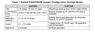
I have connected m-m banana jack connectors from PGA970EVM board (J20 and J21) to the power supply. The voltage that I have given is 12V DC. I could not get the required regulated voltages at Avdd and Dvdd pins. Is there any external supply that should be given for Avdd to show 3V and Dvdd to show 1.85V? Should I short J11 and J12 pins? 

Thanks & Regards, 

Divya

  • Hi Divya,

    No external power supply is needed for the AVDD and DVDD pins. They are supplied internally from the PGA970 itself.

    J11 and J12 are related to the DAC output and should not affect the powering of the PGA970. Please make sure your other jumper settings are set to the default configuration:

    Please also make sure that power is being applied to VDD. You can probe directly at pin 20 of the PGA970. 

    If you have not already, please refer to the PGA970EVM user's guide for more information about working with the EVM. You can find the user's guide in the my secure resources folder along with the PGA970 datasheet.


    Regards,

    Scott

  • Hi Scott, 

    The jumper settings are set to default configuration. Power is also being applied to VDD. After going through the PGA970 datasheet, slds201a, I have enabled few features. Yet, the Avdd and Dvdd vales are not coming up to their voltages. Are there any extra configurations to be set on the GUI or USB2ANY explorer? It seems like the power at VDD is not being supplied to all the pins of PGA970.

    Thanks & Regards,

    Divya

  • Hello Divya,

    What kind of current draw do you see when you apply power to the PGA970EVM? It sounds like there is some problem with the power to the PGA970 or the part itself. Can you also try to measure the voltages for VDD, AVDD, and DVDD directly at the pins of the PGA970 if you have a small enough probe?

    Regards,

    Scott

  • Hi Scott,

    The product was purchased recently. I too feel that the PGA970 is not getting enough power. The current draw for 12V is 0.05A (cv mode in power supply), The voltage directly at the pins of VDD is 12V, AVDD is 0.0025V, DVDD is 0.0184V. Should there be a constant current of 0.1A for the PGA970? 

  • Hello Divya,

    The current draw can vary depending on the load on the primary LVDT supply, the demodulator settings, and the output stage settings, but a total draw of 50mA is not unreasonable for the EVM. Do you have a sensor connected? Are you able to communicate with the EVM through the GUI?

    Can you please post a picture of your EVM?

    Regards,

    Scott

  • Hi Scott, 

    The above picture is how my setup is currently. I have not connected any sensor. I am able to generate a sine wave but unsure if the EVM is communicating with the GUI properly. 

    Thanks & Regards, 

    Divya

  • Hi Divya,

    The board setup looks just fine. The simplest way to determine if the GUI is communicating properly is to command a DAC output and measure the result at the VOUT pin. On the DAC settings page, click DAC_ENABLE, TEST_MUX_DAC_EN, and set the DAC REG0 to some non-zero value while monitoring the voltage on VOUT. If the communication is working properly you should see the voltage change as the DAC REG0 value is changed.

    If are you are able to generate a sine wave using the GUI, then the device should be communicating properly.

    Regards,

    Scott

  • Hi Scott, 

    I tried checking the DAC output on the VOUT pin by making the changes as you stated above. The GUI does not seem to be communicating with the board as there was no change at the VOUT pin. I tried using USB2ANY Explorer v2.6.3.2 to check if the USB2ANY is working properly and it is. On that i could change the DAC0 and DAC1 voltage values and check at J3 (which was showing the voltage values corresponding to the register values). 

    Any idea what might be the problem? Are there any firmware changes to be made or is there a new version of the GUI? 

    Regards, 

    Divya

  • Hi Divya,

    When you mentioned that you were able to see a waveform, does that mean that you were able to configure a waveform through the GUI and generate it as described in the GUI User's Guide? Or does the waveform output on P1 get generated on startup?

    If you have not done so already, please follow the instructions in the EVM GUI User's Guide to generate a waveform and confirm it is being produced as you have configured it. You should not be able to navigate to the correct GUI pages unless the digital interface mode is activated, although that is not necessarily a guarantee that communication is happening properly.

    Regards,
    Scott

  • Hi Scott, 

    The waveform output is generated on startup. I have followed the instructions from the GUI and generated the waveform accordingly but I am unsure if the communication is actually happening with the board. 

    Also, does the example firmware enable communication with the PGA970evm board and the GUI or do we have to develop a firmware on our own? And to develop our own application is the XDS200 JTAG emulator necessary to use code composer studio?

    Regards,

    Divya 

  • Hi Divya,

    The firmware is independent of the EVM/GUI operation unless you disable the digital interfaces via your firmware. If you are able to generate a waveform via the GUI, then that means the EVM and GUI are communicating properly. If there is already a waveform on startup,  I would just recommend checking that the waveform you generate from the GUI procedure actually matches the correct frequency that you specified. Choose a frequency different from the one that is generated on startup.


    Regards,

    Scott

  • Hi Scott, 

    After checking the generated waveform from the GUI, It is seen that the signal getting generated is just noise. It does not match with the frequency that I have given to generate waveform. The PGA970EVM does not seem to be communicating with the GUI through USB2ANY. Is there any firmware to be loaded to enable the basic usage? 

    Regards, 

    Divya

  • Hi Divya,

    You should not need any firmware to communicate with the PGA970 through the digital interface while using the EVM and GUI. It seems like there may be some damage to your PGA970EVM. I recommend contacting the vendor where you got the EVM to exchange this for a replacement.


    Regards,

    Scott