This thread has been locked.

If you have a related question, please click the "Ask a related question" button in the top right corner. The newly created question will be automatically linked to this question.

[FAQ] My Inductive Sensing EVM won't connect to the GUI. How can I fix it?

Other Parts Discussed in Thread: LDC1314EVM, LDC1000EVM, LDC1614EVM, LDC1101EVM, LDC2114EVM

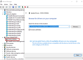
Many of the inductive sensing EVMs can utilize the same debugging process to solve an issue where the EVM won't connect to the GUI. This post will talk about the different possibilities and how to resolve them. 

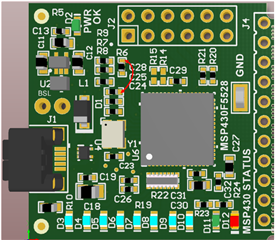
This guide applies to inductive sensing EVMs that use the MSP4305528 in their EVM. Generally, these EVMs use the Sensing Solutions GUI. This includes but is not limited to:  LDC1000EVM, LDC1314EVM, LDC1614EVM

  • In the case that an inductive sensing EVM isn't communicating with a PC, it is usually one of three main causes, a failed firmware update, a failed driver install, damage to the board. In the case that the board is physically damaged, there isn't much that can be done but there are steps that can be taken to solve the first two issues.

     In the case of a failed driver install, the proper EVM driver is included with the Sensing Solutions GUI. You can manually update the EVM's USB driver through the device manager with the driver file being located at C:\ti\Sensing Solutions EVM GUI-1.10.0\EVM Driver if the GUI was installed in the default location. The files name is evm.inf. Note that '1.10.0' is the sensing solutions GUI version so it may change depending on which version you installed.


    In the case for a failed firmware update, the best option is to reflash the EVM by putting it into BSL mode and using a separate tool to flash the MSP on the board. Here are the steps to do that:

    • Step 1. Putting the EVM in to BSL mode by connecting the MSP PUR pint to VUSB.
      • The goal of this is to connect the MSP PUR pin to the VUSB pin on the MSP430. Since connecting to the pins of the MSP is difficult, we can short the connection between a resistor and a capacitor that are connected directly to these pins instead.
      • The LDC1614EVM revB can be put into BSL mode by connecting R6 to C29 as shown below:
      • The LDC1000EVM can have the same PUR connection by connecting C6 to R40 as shown below:
      • The LDC1101EVM PUR connection is between R12 and C14 as shown below: 
      • The LDC2114EVM PUR connection is between R6 and C28 as shown below: 
      • Make sure that the connection is shorted while the EVM is being connected to the PC so that the MSP goes into BSL mode on startup.
    •  Step 2. Download the Python Firmware Upgrader
    • Step 3. Flash the EVM
      • Connect the EVM to the PC
        • Once the EVM is powered on and in BSL mode, the short between the pins can be removed.
      • Run Python_Firmware_UpgraderGUI.exe
      • If the device is connected and in BSL mode the screen should display "ready..."
      • If this is not the case, ensure that the device is in BSL mode (no LEDs will be on) and click File -> Rescan HID Bus
      • Choose File -> Open User Firmware and navigate to the proper EVM firmware file
      • The Sensing Solutions GUI comes with the most up to date firmware files in the following folder path: C:\ti\Sensing Solutions EVM GUI-1.10.0\EVM Firmware.
      • When successfully completed the screen should read "Programming: OK"

    At this point, the EVM should be recognized by the Sensing Solutions GUI and connect properly.

     If you have any questions, feel free to ask a new question. 

    Best Regards, 

    Justin Beigel