This thread has been locked.

If you have a related question, please click the "Ask a related question" button in the top right corner. The newly created question will be automatically linked to this question.

TMCS1107-Q1: Regarding TMCS1107 current sensor output

Part Number: TMCS1107-Q1
Other Parts Discussed in Thread: TMCS1107

Hello,

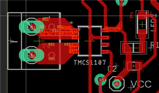
  I need to measure current for my application and for that purpose I chose this current sensor and so was currently testing it. I created a small pcb circuit for my application as follows : 


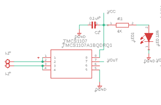
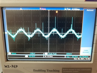
I was testing this circuit but was facing some issues. As per instructions I connected a 0.1 uF capacitor b/w Vss and GND and an LED for just power indication. But in my output at 0 A it is Vcc/2 as expected but when I connect a load then it is not able to measure the current properly. Mostly through my observations it was displaying noise and also the frequency from the output was not 50Hz, frequency measured was in Khz for some reasons.

Where am I going wrong here? Is there some other connection required?

Thanks

Avinash

  • Hello Avinash,

    What is the current you are running through the device.  Have you calculated the expected output.  Also there is some noise at the output that could be expected.  See the bottom of this post to calculate the noise expected.  (Patrick Simmons post)

    https://e2e.ti.com/blogs_/b/analogwire/posts/how-zero-drift-hall-effect-current-sensors-improve-system-accuracy-reduce-form-factor-and-simplify-design

  • Hello,

      Currently I connected a bulb as my load which usually draws around 1.2 A rms current. Previously I used ACS712 current sensing module for this application but due to unavailability in market, I had to find an alternative one for my application. The ACS712 current sensor was detecting the current properly and also giving 50Hz frequency. But when I connect the TMCS1107 current sensor, it is not giving  50Hz signal. The frequency turns out to be in KHz for some reasons. Also the mV of current measured was around 150-200mV with sensitivity of 50mV/A, which would be a current of  4A in this case which seems wrong.

    Also I understand some noise would be present as the current is measured in mV's but in this case atleast frequency must be 50Hz? But I was getting frequency in KHz.

    Thanks

    Avinash

  • Avinash,

    Do you have a filter at the output?  How are you measuring the frequency?  Their is a output that moves like seen in this post.

    https://e2e.ti.com/support/sensors-group/sensors/f/sensors-forum/910592/tmcs1100-output-current

    This is normally much higher frequency than that of the signal and can be averaged or filtered out.  If you filter this out you may get what you expect.

  • Hello,

     Currently I have not connected any filter to the output. According to TMCS1107 evm board design files , Vout was connected via 0 ohm but is that needed?

    I am measuring frequency via oscilloscope where in I am getting 1KHz-50KHz or so but actual given frequency is 50 Hz. Also as we can see from the following figure the time period the oscilloscope shows is 20ms i.e. 50Hz but in the same time oscilloscope displaying wrong frequency.

    Is the output correct? also I'm sending 1.2V rms so from sensitivity of 50mV/A I am getting the amplitude of current bit higher in this case?

    Thanks

    Avinash

  • Avinash,

    So this is a noise issue and you can use the filter.  The EVM has a 0 ohms as this will not limit the bandwidth.  I would place a simple RC filter down to the value you fell like it would clean up your signal while still allow for you to measure changes in current fast enough.

    As for the gain the layout and how you approach your device could vary the gain a little as it can change the field seen at the hall sensor.