This thread has been locked.

If you have a related question, please click the "Ask a related question" button in the top right corner. The newly created question will be automatically linked to this question.

LDC0851EVM: about ADJ_SW OF LDC0851EVM

Part Number: LDC0851EVM
Other Parts Discussed in Thread: LDC0851

Thank you very much for your help.
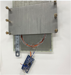
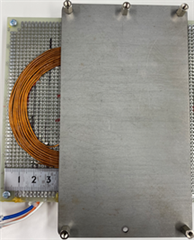
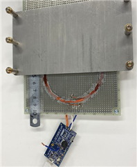
I am evaluating a prototype coil using LDC0851EVM, but I cannot change the detection distance of the target object using the ADJ switch.
However, I cannot change the detection distance of the target object by the ADJ switch.

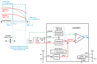
In threshold adjustment mode, is it absolutely necessary that the inductance of the sensor coil is larger than the inductance of the reference coil?

Please tell me the reason why changing the detection distance by the ADJ switch does not work.
Please let me know the cause of this.

Thank you in advance.

  • This is an additional contact.

    Actually, I have produced coils with inductance of 20μH and 24μH separately from the prototype coil described in the previous e-mail.

    In addition to the prototype coil described in the previous email, I have also manufactured coils with inductance of 20μH and 24μH and experimented with sensing operation.

    At that time, I was able to change the sensing distance using ADJ_SW.

    Currently, I have a JP line to connect the oscilloscope to the GND pin of the LDC0851EVM.

    Is it possible that this is affecting the input of the ADJ_SW?

    Translated with www.DeepL.com/Translator (free version)

  • Hello, 

    The LDC0851 requires the sensors to be the same in terms of inductance when considering them in free space. When you look at a stacked design, the targets impact will be greater on the sensor coil than it will on the reference coil. As the target impacts the sensor more, the inductance of both will decrease, but the inductance of the sensor coil will have a greater shift than that of the reference coil. 

    The ADJ setting is used to lower the reference coil inductance in the comparator to set the switching distance. 

    What is your motivation for using this large of a sensor coil rather than a smaller coil that is centered at where you need the switching distance? It is hard to tell from the photo, but the target height does not seem to be very large. 

    Best Regards, 

    Justin Beigel

  • Justin Beigel Thank you for your reply.

    1. Answers to your questions

    The reason for wanting to use a large coil is that the shape of the detection target is large (a mold used in metal processing of industrial machines), and in most cases the shape of the detection target has irregularities, so the shape of a proximity sensor can be created.

    I just want to be big. Also, since we want to detect the close contact with the detection target, we want to switch the sensor at a close distance (0.7 to 0.8, ... 2,2 to 2.3) with the ADJ.SW setting. I think.

    2. Comparison with similar coils

    As I think I posted before, I am conducting an experiment using a coil with the same outer diameter of φ90 and a number of turns of 14 turns (5 turns this time). It was possible to change the detection distance by ADJSW from a close distance. The differences from this time are as follows. (→ is this time)

    ① Number of turns (14 → 5)

    ② Enamel wire diameter (0.914mm → 0.8mm)

    ③ The measured inductance is the sensor + reference coil (73 μH → 23 μH)

    【BEFORE】

    【NOW】

    But are there any of these factors that prevent ADJSW from working?

    With the above, please point out the points for improvement necessary to achieve the goal and the points to be confirmed.

    Thank you.

  • 先のメールが届きましたでしょうか?

  • We will add and contact you. I actually measured the inductance of the φ90 coil this time. The sensor coil was 5 μH and the reference coil was 5.3 μH. The difference in inductance of 0.3μH is the detection distance by ADJSW. Is it a factor that cannot be adjusted? Or, when using a large coil of φ90 size, the coil Is it necessary to increase the number of turns to increase the inductance? I haven't received the confirmation email after making an inquiry, but please contact me.

  • Hello, 

    The difference between them could be the reason you are not able to see the change. If you switch which coil is sensor and which is reference, does your output state flip? Also, have you verified the sensor oscillation on an oscilloscope for this coil? 

    Best Regards, 

    Justin Beigel

  • Thank you for contacting us. In the sensing experiment after assembling the coil, I remember that the output of LDC0851EVM was in the detection OFF state and was ON output. Is this state correct? By the way, with the first prototype coil whose detection distance could be changed by ADJSW When I compared it, I noticed that the sensor coil was clockwise, but is this the reason why the detection distance cannot be changed? LSENSE and LREF both when the target object is detected OFF and when it is detected ON The oscilloscope waveform looks normal. --- Is the coil design procedure you contacted in the previous email correct? Please point out.

  • Hello, 

    Yes, when the target is not within the detection distance, the output of the LDC0851 is HIGH. 

    The coil winding direction is most important when using multi-layer coils: 

    But whether you start clockwise or counter clockwise is not important. 

    As for your coil design, having that few turns means that your coil fill ratio is outside our standard recommendations. This may be why the newer sensor is not yielding an output. Do you have a need to change from the design with more turns? 

    Best Regards, 

    Justin Beigel

  • Justin Beigel Thank you for your clear answer. The reason for reducing the number of turns in the second prototype coil is that of the prototype coil. This is because the detection distance was large. As a way to reduce the detection distance The outer diameter of the coil should be small, but since the mold of the detection object is large, we want to make the sensing coil as large as possible. Detects a large target (φ90) with a maximum of 2.3 mm How should the coil be designed to achieve this?

  • Hello, 

    I think you would be better off using a smaller coil and centering it around where your mechanical threshold is. Your coil does not have to be as large as your target and if you are worried about part to part variation, you could implement a dual detection so that if the target is closer to the sensor in some areas, then you have two points of detection to counteract this. If you do implement multiple LDC0851s, then I would not go above 30mm coil diameter and keep them separated by at least 10 mm (>30%) to avoid cross talk. 

    For detecting the target, the distance between the coil and target is what drives the need for coil diameter. 

    The larger this distance, the larger the coil size needed to maintain high enough resolution. Since your axial distance is fairly small and you are focusing on a sliding application, then you don't need that large of a coil to get your switching distance to work. Ideally, in this type of application, the axial distance is around 20-30% of the coil diameter. From there, you can position the sensor and adjust the ADJ pin to achieve the correct sliding switching distance. 

    Best Regards,