


For the second example, we will emulate a mechanical slide by movement similar to what can be found in analog dimming switches. Advantages of this implementation include a PWM output signal, and no mechanically wearing items. The use of this hall sensor enables the PWM output to be fed into a microcontroller without requiring an ADC or external signal chain components.
For the simulation, we will implement a NS facing cylinder magnet moving slide-by near a linear PWM ratiometric hall sensor. The magnet is a N42 cylinder with a 5mm radius and 5mm thickness. The displacement dimensions range from -10mm(d1) to 10mm(d2) with no X or Y offset from the center of the package. The DRV5057A ratiometric PWM output hall sensor will be used for the simulations. Alternatively, the DRV5055A can be used if analog output is required. Figure 1 displays the input configuration for the simulation. Enter desired configuration settings into the tool, and generate results for the simulation by selecting “Calculate B-Field & Vout”.
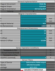
Figure 1: Slide-By Magnet Implementation
Figure 2 demonstrates the physical movement for the slide-by simulation.
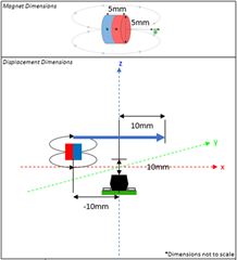
Figure 2: Simulation Movement Representation
For complex magnet shapes such as the cylinder and sphere, FEMM will be used for the magnetic field simulations. Following the selection of “Calculate B-Field & Vout”, a popup will appear requiring naming for the FEMM project and a selection of file location for the results. Populate these fields, and select “Next”.
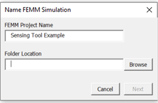
Figure 3: FEMM Simulation Folder Location
Select “Open FEMM” in the popup to start the simulation.
Before the simulation concludes, a popup will appear allowing the user save an image of the flux density plot from the FEMM simulation.
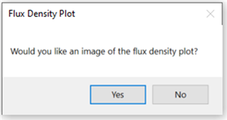
Figure 4: Flux Density Plot Prompt
Select “Close FEMM” to view the results in Excel.
Figure 5: FEMM Close Prompt
The below waveform represents the sensor output in % PWM plotted with respect to horizontal magnet position.
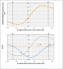
Figure 6: DRV5057 Output Results
As displayed in Figure 6, the PWM duty cycle varies with respect to horizontal magnet position varying from approximately 25% to 75% duty cycle. The analog PWM range can be adjusted via device selection, or by altering the magnetic characteristics of the simulation.
For more information on Slide-By sensing, see this Application Brief on the topic: Tracking Slide-By Displacement with Linear Hall-Effect Sensor
Previous FAQ, Part one: Simulating head-on movement with a unipolar switch.
Next FAQ, Part Three: Simulating hinge movement with an Omnipolar hall-effect switch
