


For this example, we will emulate a mechanical hinge movement similar to what is used in consumer laptops for lid position sensing. Advantages of this implementation include small form factor design, and ease of assembly/implementation. The use of the omnipolar switch enables the same output at BOP and BRP regardless of the magnet being north or south oriented. The omnipolar switch selection makes assembly of mechanical systems easier as the magnets do not need to be oriented one specific way for the device to function properly; nor does the sensor have to be adjusted or programmed to be used with the specific magnet north/south pole orientation.
In the tool, we will implement a north or south facing block magnet moving on a 200mm arc radius hinge near an omnipolar switch. The magnet is a N35 block with 2.5 mm length and 5mm dimensions for width, and thickness. The displacement dimensions range from 20 degrees (d1) to 0 degrees(d2) with a -8mm sensor Z-offset. The TMAG5231B1 omnipolar switch in SOT-23 package will be used for the simulations. To prove operational characteristics of the omnipolar switch, results will be created for both a north and south oriented magnet. Figure 1 represents configuration settings for a south facing magnet, and Figure 2 represents north facing. Enter desired configuration settings into the tool, and generate results for the simulation by selecting “Calculate B-Field & Vout”.
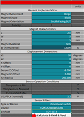
Figure 1: South Facing Magnet Implementation
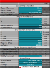
Figure 2: North Facing Magnet Implementation
Figure 3 demonstrates the physical movement for the hinge simulation.
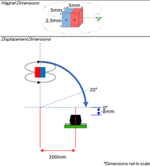
Figure 3: Simulation Movement Representation
The below waveforms represent the sensor output and B-Field plotted with respect to hinge angle.
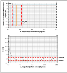
Figure 4: South Facing Magnet Output Results
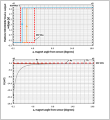
Figure 5: North Facing Magnet Output Results
As displayed in Figure 4 and Figure 5, the output results are identical for the omnipolar device regardless of magnet N/S orientation.
For additional information on hinge transition detection, see this application brief on the topic: Transition Detection Using Hall-Effect Sensors
Previous FAQ, Part Two: Simulating Slide-By movement with a ratiometric PWM sensor
