Other Parts Discussed in Thread: AWR1642,
Hi TI expert,
My customer had some problem about the heatmap crash issue, and would like to consult the debugging opinions.
When the RADAR system operates for a while, randomly, the heatmap suddenly turns to all red color (all high peak values) and loss the normal detect ability randomly. When this symptom happens, it will need to reset the chip for recovery. BTW, The normal heatmap figure is with blue color in background.
We think this issue should happened before "FFT block" , something wrong in "Mixer" or "ADC" part . Please see the video as attach in Google Drive below:
https://drive.google.com/file/d/1ZEB0WEy4ntwcvNNbh_RUxCVNgBzooy9r/view
Is this kind of chip crash?
Which part should I debug for?
Chirp parameters?
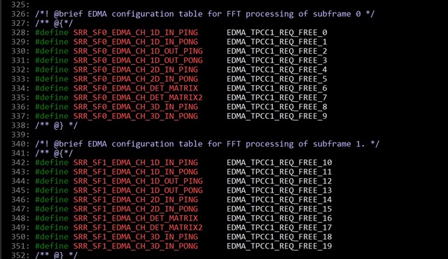
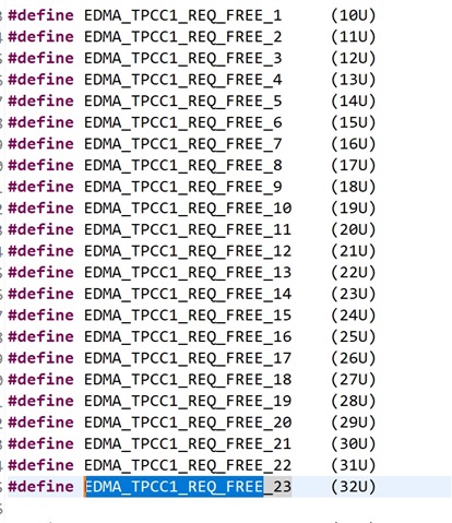
EDMA?
PS: The lab code is based on "ti\mmwave_automotive_toolbox_2_9_1\labs\lab0002_short_range_radar".