This thread has been locked.

If you have a related question, please click the "Ask a related question" button in the top right corner. The newly created question will be automatically linked to this question.

interfacing launchpad to sensor TMP121

Other Parts Discussed in Thread: TMP121, TMP123, MSP430F2013, MSP430G2231

Hi,
I'm trying to interface the kit launchpad  to sensor tmp121
and I'm not getting satisfactory results, can someone help me please.


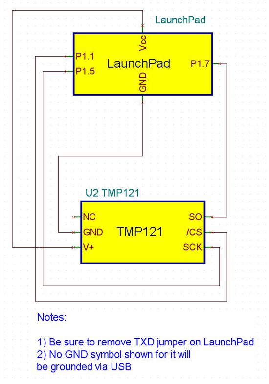
//        TMP121                   | |  MSP430F202231     |
//    -----------------------------------------------------------------   
//   |        P5               CS|  <---  |  P1.1                       |
//   |        P6  DATAOUT|  --->   | P1.7/SOMI    P1.0|-->LED
//   |        P4             CLK|  <---  | P1.5/SCLK           |
//

//******************************************************************************


#include <msp430x20x3.h>

void main(void)
{
  int i;
 
  WDTCTL = WDTPW + WDTHOLD;     // Stop WDT
 
  DCOCTL = CALDCO_1MHZ;
  BCSCTL1 = CALBC1_1MHZ;
 
  P1OUT = 0;
  P1DIR |= 0x03;
  USICTL0 |= USIPE7 + USIPE5 + USIMST + USIOE;        // Port, SPI master
  USICTL1 |= USIIE;                                                                  // Counter interrupt, flag remains set
  USICKCTL = USIDIV_2 + USISSEL_2;                               // /4 SMCLK
  USICTL0 &= ~USISWRST;                                                    // USI released for operation
  USICNT =  USI16B + 16;                                                       // init-load counter
   P1OUT |= 0x02;                                                                      //init sensor convertion
  _BIS_SR(LPM0_bits + GIE);                                                 // Enter LPM0 w/ interrupt
}

// USI interrupt service routine
#pragma vector=USI_VECTOR
__interrupt void universal_serial_interface(void)
{
  int aux, i;
  float tmp = 0;
 
  P1OUT &= ~0x02;                            // init data transfer
  for(i=0x100;i>1000;i--);                    // delay for data transfer

 
  aux = (USISR >> 3);
 
  if (aux & 0x1000)                           //for a negative value
  {
     aux ^= 0x1FFF; 
     aux += 0x0001;
  }

  tmp = aux/16;
 
  if (tmp > 15)                                         // if temperature > 15 deg celcius set led 
    P1OUT |= 0x01;
  else
    P1OUT &= ~0x01;
  P1OUT |= 0x02;                                     //start new convertion
  USICNT = USI16B + 16;                      // re-load counter
}


COMMUNICATING WITH THE TMP121  (datasheet)

The TMP121 and TMP123 continuously convert temperatures to digital data while CS is high. CS must be

high for a minimum of one conversion time (320ms max) to update the temperature data. Reading temperature data

from the TMP121 and TMP123 is initiated by pulling CS low, which will cause any conversion in progress to

terminate, and place the device into analog shutdown. Quiescent current is reduced to 1 u

A during analog

shutdown. Once CS is pulled low, temperature data from the last completed conversion prior to dropping CS is

latched into the shift register and clocked out at SO on the falling SCK edge. The 16-bit data word is clocked out sign

bit first, followed by the MSB. Any portion of the 16-bit word  can be read before raising CS. The TMP121 and TMP123

typically require 0.25s to complete a conversion and consume 50 u

A of current during this period. If CS is held

high for longer than one conversion time period the TMP121 and TMP123 will go into idle mode for 0.25s,

requiring only 20 u

A of current. A new conversion begins every 0.5s.


  • Hello brighenti,

    I am working on this and will get back with you shortly.


  • Hello brighenti,

    As I started looking into this, I noticed that in the comment section of your code you specify the MSP430F202231.  Can you please verify that is the correct part number?  I assume by your header that it's probably the MSP430F2013 or similar.

    Can you also clarify what you mean by 'not getting satisfactory results'?  Is this an SPI communications issue, TMP121 accuracy issue, etc.? 


  • Pete Semig
    thanks for your attention.

    made ​​a mistake when typing the comment. The kit I'm using is the Launch Pad. The partnumber is MSP430G2231.

    when I stop execution at the line aux = USISR; USISR register contains values ​​that do not reflect the ambient temperature. values ​​either below zero or very much above zero. And the value does not change over time, I even heating or cooling the sensor. So I'm thinking that the value that sometimes appears in USISR is some garbage.

    I wonder if the SPI code for reading the sensor is correct or is missing something?


    again
    thanks

  • hey pete

    you stopped answering me, why?
    I need your help. please ....

  • Hello brighenti,

    Sorry for the delay.  In order to help you most effectively, I had to order a LaunchPad and TMP121.  I have just received them and continue to work on your request.  I will have results today or tomorrow.


  • Oh Pete,

     thanks a lot man.

     I'll be looking forward to your response.

  • Hello brighenti,


    Working code is attached.  It provides you with a good starting point.


    Here are a few points to make:

    a)      This code only takes 1 measurement at a time.  

    b)      Be sure to remove the TXD jumper from the LaunchPad so you can use P1.1.  Or, just modify the code and use P1.4 or similar.

    c)      Also, I used the VCC pin from the LaunchPad to provide the supply voltage for the TMP121.

    d)      I used IAR.  Once you Download & Debug, Go, then Break the program (for it will be stuck in the while(1) loop).  Then check the contents of USISR.  To do that you can go to View->Register and select “USI” from the drop down menu.

    e)      Now you can heat/cool it, redo part d, and the value will change.  I noted the value in USISR went up when I heated it and down when I cooled it. 


    From here you can modify the code to take continuous readings (be aware that it takes up to 320ms per conversion…hence the delay).  For example you could add a timer or connect the CS to the pushbutton.  Please post your code if you make such modifications.  You can also add code to convert the 13 most-significant bits from USISR to your desired temperature scale.


    Hope this helps!

  • Pete
    thanks for the help and sorry for my naivety, but I would understand some lines in your code main.c


    1)  In the slau144h.pdf on page 404, item 14.2.3.1 SPI Master Mode, I understood that after pulling CS low, required at least 16 clock pulses to the bits of the slave (TMP121) were transferred to the Master (USISR LaunchPad) and so the data would be available in USISR, then what is the purpose of the command USISR = P1IN?

    2) if TMP121 temperature data are 16bits, why did you set the USICNT only 16 and not USICNT = USI16B + 16;

    3)  I removed the TXD jumper from the launchpad and connected the tmp121 the same way you do it.
    I am running the code attached and still not get correct values ​​of temperature.
    you could run my code and verify, please, what is still wrong.
    If my code is correct, I can only believe that my sensor was damaged when a soldier in the circuit.

    thanks a lot for help.

    brighenti

  • Hello brighenti,


    To be upfront, I am not very adept at programming.  


    You’re right…you can comment out USISR=P1IN if you like.  I also tried USICNT=USI16B+16 and obtained good results.


    I created a new project with your code in IAR EW.  Upon compile I received a warning that “i” was declared but never referenced.  Upon download & debug I watched tmp and aux.  No valuable data was found in either.  I also looked at USISR…it contained all 0’s.


    Therefore I suggest using the code that I provided (with or without your aforementioned modifications) and verify your setup.


    While the setup is pretty straightforward, be sure that you ground the TMP121.  I used the ground pin from the LaunchPad.  Here is a sketch of my setup.  Please verify your connections.


  • Pete, Now yes!

    it worked very well.

    The code that I want to run, is what I have attached in my last post.
    I used this code that you attached in your post.

    I found that my soldering was sloppy.

    thanks a lot for help and attention.

    regards,

    brighenti.