


Other Parts Discussed in Thread: DRV5012, , TMAG5111
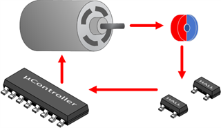
Traditional window blinds are used to shade buildings by blocking the light coming through the windows. By placing a barrier between the window and the rest of the building, it can help maintain the temperature indoors and save on heating and cooling costs. These blinds are typically lowered by manually pulling on a string or directly on the blind. Motorized window blinds offer an ease of use by having a motor attached to a roller that is controlled by a remote or cell phone app which sends a signal to the blind to move up, down, or to a preset position. The figure below shows a diagram of the functionality of a Hall-effect sensor system in a motorized window blind.
Motorized blinds need to constantly know their position so the motor will not be strained when reaching the end of travel in either direction. The blinds also need to recognize when they have been manually pulled down so the end of travel is not shifted for the current position. This is especially important when the user is lowering the blinds remotely and may not be close enough to be alerted if the motor is being strained.
Hall-effect latches can provide exact position data by performing a function called rotary encoding. Incremental rotary encoders translate rotational movement into electrical signals for more precise control of automated systems. As rotation occurs, incremental encoders produce alternating high and low pulses which may indicate speed and direction of the rotating object. In motorized window blinds, Hall-effect latches can keep track of the changing polarity of a ring magnet that is attached to the shaft of the motor. This will indicate the number of rotations of the motor and this information will allow the system to know the speed and position of the blind. For this type of application where the shade will be moving in two different directions, either two single axis latches or one two-dimensional latch can be used to indicate the position of the blind.
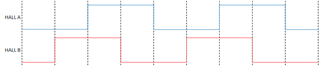
When using two single axis latches, such as the DRV5012, to determine direction it is important to place the sensors precisely to achieve the optimal 90-degree quadrature offset. The 90-degree offset is attained when the sensors are separated by half the length of each magnet pole plus any integer number of pole lengths. Having the ideal 90-degree offset maximizes the timing margin between each state, which prevents errors due to mechanical tolerance, sensor mismatch, and signal jitter. The output signals below are an example of a 2-bit quadrature output that clearly show the four different states.
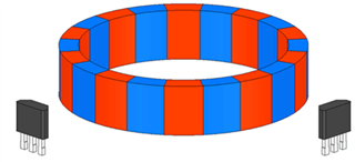
If there are errors in detecting the change in direction this can cause the motorized blind to lose its position and incorrectly detect the end of travel. The figure below shows the sensor configuration in relation to the ring magnet to achieve a 90-degree offset.
The DRV5012 device is an ultra-low-power digital-latch Hall effect sensor with a pin-selectable sampling rate and is recommended for power constrained applications such as battery powered window blinds.
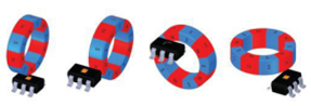
Another solution is to use a 2D Hall-effect latches, such as TMAG5110 or TMAG5111, which simplifies the design further and provide more flexibility in sensor placement. By integrating a second hall element which is sensitive to an orthogonal component of the magnetic field vector, a single device can be used to measure the speed and direction of the rotating magnet. This is possible due to the natural effect of the magnet to produce field components which are 90 degrees out of phase. This eliminates any errors that can occur due to placement of two single axis sensors. The figure below highlights the flexibility in sensor and magnet placement when using a 2D latch.
Using one 2D latch and reduces board space compared to using two single axis latches. This is beneficial for size constrained applications such as motorized window blinds. TMAG5110 has two output signals that represent the response of each independent hall element. To simplify your design further, the TMAG5111 also has two output responses that represent the speed and direction of the magnet.
