This thread has been locked.

If you have a related question, please click the "Ask a related question" button in the top right corner. The newly created question will be automatically linked to this question.

FDC2114EVM: How to increase sensitivity

Part Number: FDC2114EVM
Other Parts Discussed in Thread: FDC1004, FDC2114, LDC3114-Q1, FDC2114-Q1

Hello, teams.

I use FDC2114EVM  for touch sensor to On/Off LEDs.

10x10 square pcb is attached 3T ABS plate.

like this

finger                 ↓

3T ABS plate =======  

10x10 PCB         ***  

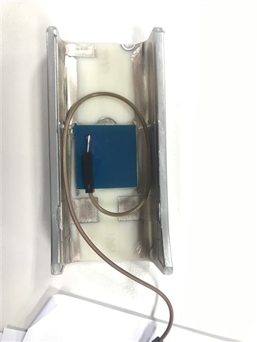
When finger touch a plate, sensor value is change 550 to 548. (In my test condition)

but a wire around below the PCB, sensor value is change 550 to 530.

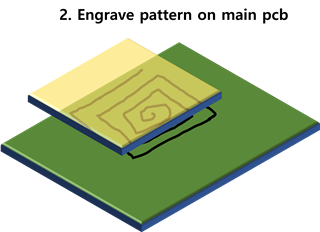
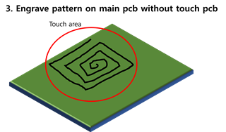
Maybe when I make a 10X10 engraved pattern PCB, It also expect same effect?

Best regards,

Kim.

  • Hello Kim, 

    You could add shielding to your sensor implementation to reduce the impact of the cable on the opposite side of the sensor. This allows for the sensor to be most sensitive in the desired sensing direction. See this E2E blog for more information on how shielding can help here. 

    Additionally, we have the FDC1004 available which has an active shield driver integrated into the device. 

    Best Regards, 

    Justin Beigel

  • Hello Justin,

    Thank you for your suggestion.

    Actually I want to improve the impact of the cable on the opposite side of the sensor.

    To explain a brief structure,

    The sensor will be attach above a other main PCB or engrave.

    And main PCB place below the plate.

    If user touch the sensor area, pcb turn on led via FET. (MCU control FET)

    So when I test a sample system.

    In case a cable doesn't exist below sensor, FDC2114 output value is unchanged or small. It is impossible to distinguish whether the user has touched it or not.

    Other case a cable exist below sensor like above picture, FDC2114 output value is improved.

    But I can't use that kind of cable in the product, I wonder engrave pattern on pcb is effective below 3 cases.

    or Please let me know if there is any other good way.


    Lastly FDC2114/FDC1004 is not AEC-Q product, can you recommend AEC-Q product?

    Thank you for you kind.

    Best regards,

    Kim

  • Hello Kim, 

    Thank you for the clarification. If the cable is acting as an additional antennae for your sensor, your main concern is increasing sensor sensitivity. The FDC2114 operation on a resonant architecture to determine the change in capacitance. You could try adjusting the LC tank on the EVM to change the sensor frequency to be more sensitive to the change. I would start by decreasing the capacitor on the EVM. You could also try a grounded target approach to increase sensitivity to user touch. 

    Alternatively, since this is a touch application, you could use an inductive touch button instead. This would be a different approach to design here but uses the force of the press rather than the capacitive change to determine a button press. In order to know if this will work, I have a couple questions:

    • What is the thickness of your ABS?
    • Is ABS the final material for this application? 
    • Is the entire structure ABS? The picture looks like there might a different material on the sides of the sensor. 

    Our getting started material for inductive touch buttons can be found here: https://e2e.ti.com/support/sensors-group/sensors/f/sensors-forum/1086430/faq-how-to-get-started-with-inductive-touch-buttons/4022125

    Lastly, the FDC2114-Q1 is an AEC-Q version of the FDC2114. If you want to pursue inductive touch buttons, I would start by looking at the LDC3114-Q1. 

    Let me know your thoughts on the alternative suggestion. 

    Best Regards, 

    Justin Beigel

  • Hello Justin,

    Thank you for your alternative suggestion.

    Unfortunately, I can't use your suggestion. because It is specification designated by the customer company.

    Nevertheless, to answer your question

    • What is the thickness of your ABS?

               - In Demo 3T, It could be changed 2~2.5T.

    • Is ABS the final material for this application? 

               - It's going to be painted, but yes.

    • Is the entire structure ABS? The picture looks like there might a different material on the sides of the sensor. 

               - Yes, The actual product is about 1m long and white led sting in the center. It is 30cm.

                 Touch sensor placed on the far right or left.

    Anyway I try changing LC tank on the EVM and grounded target.

    Thank you for your help.

    Best regards,

    Kim.