Other Parts Discussed in Thread: TDC1000, TDC7200
Hi Expert,
My customer want to use TDC7201 in LiDAR application, and there are several questions about that.
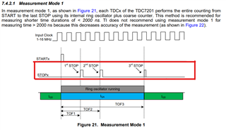
Q1. What are the exactly application about 2nd STOP to 5th STOP, as we know TOF can be simulated by the time between START to 1st STOP.
Q2. Is there a command flow chart about TDC7201 if customer do not want to use MSP430 to control?
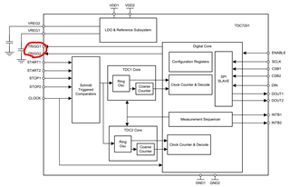
Q3. If the "Trigger " pin is not connected due to a special design problem, is there any other way to confirm the IC status?
Q4. Does it provide automatic switching between far/near mode? If not, is there any suggestion for sample code to achieve this application?
Q5. If customer not use MSP430 to control TDC, but use other MCUs to trigger the TDC7201 EVM, find that a voltage drop occured for the start_ex1/2.(3V -> 1V)
So the following problems are:
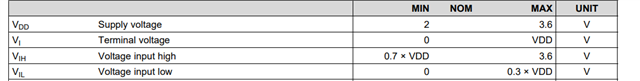
Whether the following signal pins of TDC7201 have specified voltage/time/drive current?
1- TRIG1/2
2- Start_ext1/2
3- Stop_ext1/2
Thanks a lot.