This thread has been locked.

If you have a related question, please click the "Ask a related question" button in the top right corner. The newly created question will be automatically linked to this question.

LDC3114: Tuning for spring length measurements.

Part Number: LDC3114

Hello,

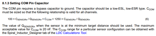
I have an application where I would like to do low power measurements of a spring's length using the LDC3114.

I have measured the the spring extended and compressed using an LCR meter and got the following measurements:

Spring Extended Measured at 1V, 125kHz
Lp 2.6606 uH
Rp 2.7786 Ohms
Qp 1.3297 Q
Ls 1.8037 uH
Rs 0.93459 Ohms
Qs 1.2126 Q
Spring Compressed Measured at 1V, 125kHz
Lp 3.4381 uH
Rp 6.2435 Ohms
Qp 2.3121 Q
Ls 2.9879 uH
Rs 0.9041 Ohms
Qs 2.0765 Q

These measurements violate the sensor parameters LDC3114 requires, namely the "5 <= Q <= 30" and "350 Ohms <= Rp <= 10k Ohms".

This generates the following questions:

  1. I realize these measurements were conducted at a lower frequency than the desired operating frequency of the LDC3114, are they of any use for tuning the sensor configuration?
  2. I understand additional inductance can be added in series with the sensor as per this blog (https://e2e.ti.com/blogs_/b/analogwire/posts/inductive-sensing-how-to-use-a-tiny-2mm-pcb-inductor-as-a-sensor),
    is it possible to add additional resistance in series with the sensor to modify it's Q factor?
  3. Any other tips for getting this spring working with the LDC3114? (i.e. selecting COM pin capacitors?)

Thanks,

Chris

  • Hello Chris, 

    The Q and Rp specifications in the datasheet are for the combined LC tank. Once you choose a sensor capacitor, then the resonant frequency of the LC tank, Q factor, and Rp can be compared to the specifications. You can use your current measurement as a baseline for determining the sensor capacitor but once you do, you can measure again at the resonant frequency. 

    In regards to choosing the COM pin capacitor, you can use the following equation to find the upper and lower bounds based on your sensor implementation. 

    Best Regards, 

    Justin Beigel

  • Hi Justin,

    Thanks for the information, I should have known it was for the whole system!

    Calculating those parameters for the combined LC tank based on the equations shown in "Sensor Design for Inductive Sensing Applications Using LDC" app note, and came to the following results, looks like a 4.7nF capacitor will work, but the resonate frequency is pretty low:

    If an adding additional series resistance is possible, adding 4 ohms in series with the inductor allows a 680pF capacitor to be used which increases the resonate frequency above 3MHz which I understand is more optimal. Is this approach viable?

    Many thanks,

    Chris

  • Hello Chris, 

    For the LDC3114, it is best to stay above 5MHz for the sensor frequency: 

    In order to meet this, you can add a series resistor or inductor to your sensor design as long as the resulting circuit still falls within the specifications for the sensor in the datasheet. For more information on adding the inductor in series, see the following post: https://e2e.ti.com/blogs_/b/analogwire/posts/inductive-sensing-how-to-use-a-tiny-2mm-pcb-inductor-as-a-sensor

    Best Regards, 

    Justin Beigel