This thread has been locked.

If you have a related question, please click the "Ask a related question" button in the top right corner. The newly created question will be automatically linked to this question.

FDC2112: FDC2112 obtain irregular jumped LC resonant frequency

Part Number: FDC2112
Other Parts Discussed in Thread: FDC1004

Hi team,

I attached two waveforms to you and  bottom waveforms in diagram are the input signal of IN0A-IN0B for FDC2112. And these two different inputs has different conditions of output frequency.


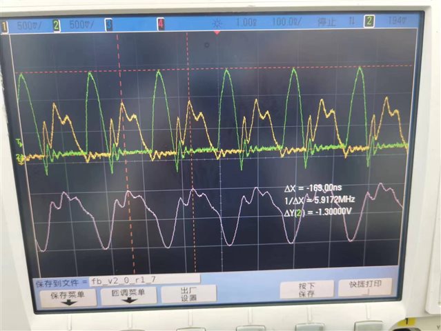
load capacitor = 70pf;  output of FDC2112 (value of LC resonant frequency) irregularly jumped.

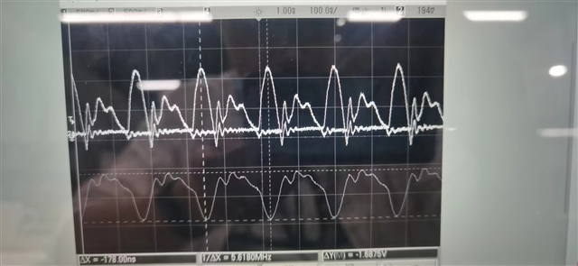
 load capacitor = 45pf; output of FDC2112 (value of LC resonant frequency) is stable.

Is it possible that it caused by the way of FDC2112 calculate LC frequency?  Could you pls help to analyze the reason?

Thanks!

Rayna

  • Rayna,

    The FDC2112 estimates the sensor signal frequency by counting the number of reference clock periods during a number of sensor signal periods corresponding to the RCOUNT setting.

    Is there a repeating pattern to the irregularly jumped frequencies in your first case (with C = 70pF), or does it seem random?

    We have found the FDC2112/4 can be sensitive to EMI, and that it can be challenging to shield the sensor.
    Is there possibly a source of EMI affecting the sensor and causing the jumps?

    Regards,
    John

  • Hi John,

    The irregular jumped frequencies are random.

    Customer suspected it caused by the mechanism of the device calculate the LC frequency cause the input signal is changing. They want us provide a block diagram to explain how device judge the LC frequency. Is that possible to provide?

    Besides, What are the recommended ways to eliminate EMI?  The input signals' shape changed because the EMI shield methods.

    Rayna

  • Hello Rayna, 

    We can't provide a block diagram for how the LC frequency works but it doesn't impact the drive of the sensor. The device has separate registers that control the current in each channel (IDRIVE) to set the amplitude of the sensor oscillation. 

    In regards to EMI, you can implement the passive filter network described in https://www.ti.com/lit/an/snoa962/snoa962.pdf. We also have a different device (FDC1004) that has a built in active shield to reduce the noise impact on the system. 

    I would also like to add that since the FDC2112 operates based on the resonant frequency of the LC tank attached to it, the capacitance of an oscilloscope probe can sometimes have an impact on the measurement. It is best to decouple the probe with a 1k Ohm resistor. Is the data from the device jumping around even when the oscilloscope is not attached? 

    Lastly, is this using the EVM or your own board design? 

    Thank you, 

    Justin Beigel