This thread has been locked.

If you have a related question, please click the "Ask a related question" button in the top right corner. The newly created question will be automatically linked to this question.

TMAG5170-Q1: more information

Part Number: TMAG5170-Q1
Other Parts Discussed in Thread: TMAG5170

I am currently working on a project that could use the TMAG5170A1EDGKRQ1 and I need more information about these components : 

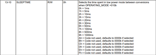
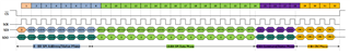
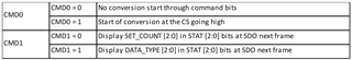
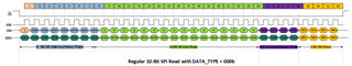
- I have difficulty to understand how we can choose the channels we want to measure and how to read and interpret the transmitted data. Can you explain me that ?

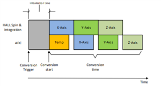
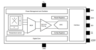
- Can you explain me how data are processed inside the component ?

- Can you give me the FIT-Rate for this component at 55°C ?

- Are filters included in the component analog or digital ?

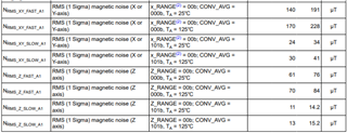
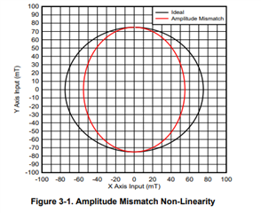
- What is the minimal magnetic field value the component can measure ? In the datasheet it is written ±50 mT, does it mean the component can measure all magnetic field in this range (even 1 mT) or is there a minimal value below which the sensor doesn't pick up the magnetic field (for example 20 mT)?

Thank you in advance for your answer. I look forward to hearing from you.


Arnaud LANDRI

  • Arnaud,

    Thank you for reaching out on E2E with your questions.

    • The Hall-effect is inherently only able to measure a single component of an applied magnetic field.  This is the result of the Lorentz force acting on a driven current through the Hall element. The resulting measured voltage in the Hall-element is proportional only to the component of the field vector orthogonal to the sensing element. You can find a more detailed description in this video:

      https://training.ti.com/intro-3d-hall-effect-sensors

      In order to measure the complete magnetic field using Hall-effect elements, it is necessary to integrate 3 separate sensors sensitive to each axis: X,Y, and Z.  To measure the complete magnitude, you would use: B = sqrt(x^2 + y^2 + z^2)

      For your particular application, you may be interested in any of these three output components, and depending on the function there are different advantages for using each.  We have a handful of brief application notes which discuss how you might use these inputs for various functions:

      https://www.ti.com/lit/pdf/sbaa513
      https://www.ti.com/lit/pdf/sboa514
      https://www.ti.com/lit/pdf/sbaa512
      https://www.ti.com/lit/pdf/sbaa503

      TMAG5170 also offers angle output, which is particularly useful detecting the position of rotating magnets.  For this function, you would select two field components which are 90 degrees out of phase and use these as inputs to the integrated CORDIC function.  The resulting output will be a measure of angle to 0.25 degree resolution.

    • In TMAG5170 each axis is sampled serially, such that only one element is active at any time.  During sampling, the voltage across the Hall-element is filtered and gained up before being sampled in the integrated ADC.  If used for angle measurements, the output data is then passed into the CORDIC engine which you can learn more about here:

      https://training.ti.com/zh-tw/cordic-algorithm-angle-calculations

      Based on the sample pattern selected for your active channels, the device will follow a pipelined process similar to what is shown here:
    • The output range of the device is programmable as either +/-25 mT, +/- 50 mT, or +/-100mT.  These represent the full scale input range of the device.  With 1x averaging, the output is naturally 12-bit, but 2x-32x averaging, the result will be oversampled and reported as a 16-bit result.  The limiting factor for your minimal measurement will be the input referred noise, which is shown in the specification table:


      For example, we see in either the X or Y direction with 1x averaging the resulting noise has a maximum RMS value of 191 uT at room temperature, but by increasing averaging to 32x the noise is effectively reduced to a maximum RMS value of 34 uT.  Your input field must exceed the observed input noise in order to produce any measurable input.  You will have a more robust system by designing for a larger SNR, but TMAG5170 is able to observe inputs < 1 mT.

    • The block diagram shows the filtering stage is in the analog domain, though you can also achieve further noise reduction through the digital averaging through the user defined number of samples (1x-32x):


    • TI has a FIT rate estimator available here, and I've already searched for the part number you are using:
      https://www.ti.com/quality/docs/estimator.tsp?OPN=TMAG5170A1EDGKRQ1&CPN=&partNumber=TMAG5170A1EDGKRQ1#resultstable

    Thanks,

    Scott

  • Thanks for your answers, they are very useful. However I need more information for the choice of the channels we want to measure and how to read and interpret the transmitted data.
    In my case, I am interested by the X and Y components of the magnetic field and I want to transmit data continuously. From what I saw on the datasheet, we need to edit registers but I don't understand how to use them. Can you show me (with a schematic or a extract of code if possible) how we can initialize the transmission of data between this component and the µC?

    Also I have another question with these registers, at the 35th page of the datasheet it is written we have to put a delay between each conversion when we are in "continuous conversion" :


    I would like to know if we really have to put this delay or if there is a possibility to remove it in order to transmit data continuously.

    Thank you in advance for your answer.
    I look forward to hearing from you.

    Arnaud

  • Arnaud,

    Sure.  To start we need to look over the format for the input word.

    The first 8 transmitted bits will specify read or write and the register address.  The next 16 bits [9:24] are the register data.  Bits [25:28] contain command bits, which are not needed at first, and the final 4 bits [29:32] are for CRC checking.  CRC gives confidence that transmitted data over SPI is sent and received by both TMAG5170 and the microcontroller correctly.  These bits are calculated based on bits [1:28] and you can find more information on that and some sample code here:

    https://e2e.ti.com/support/sensors-group/sensors/f/sensors-forum/1058986/tmag5170-tmag5170-crc-algorithm

    To setup the sampling you are describing you will need to write to registers 0x00 and 0x01

    Register 0x00 needs a value of 0b010 written to OPERATING_MODE in order to enable continuous sampling.  Leaving temperature settings as default and averaging at 1x, the resulting register input will be 0x0020.

    Register 0x01 needs a value of 0b0011 written to MAG_CH_EN to enable the XY sampling pattern.  Leaving the default +/- 50 mT input range and no angle calculations you would use an input word of 0x00C0.

    Calculating CRC codes for each, it would result with these writes

    Write command for register 0 = 0x0000200D 

    Write command for register 1 = 0x0000C002

    For the command bits, these are used primarily in trigger mode or to select STAT bits observed on SDO.  CMD3 and CMD2 are reserved bits you will always set to 0.  CMD0 and CMD1 are defined here:

    The delay you are noticing in SLEEPTIME is used for wake and sleep mode.  In this mode, the device will put itself in a low power sleep condition for a set duration, wake up for a sample, and then return to sleep.  You are then able to wake the device and read the outputs at will.  This is meant to reduce total current and is helpful in battery powered operation.  

    In continuous mode, you are free to read the outputs as often as you like, but you must wait for the conversion time to complete if you do not want to risk a duplicate reading.  The timing is described in section 8.1.3.1, starting on page 45.  In the case describe with the settings above, the conversion will be sampling both X and Y at the fastest rate.  The total conversion time should be approximately 75 us.  (50 us for first conversion + 25 for each subsequent conversion).  If you were to enable averaging, then the sample time would only increase by 50 us for each additional XY sample in the conversion. 

    During your read, you would send a read command to register 0x09 for X data, and a read command to register 0x0A for Y data. The output data will be located in bits [9:24] of the received data.

    Thanks,

    Scott 

  • Scott,

    Thank you very much for your answers, they have been very useful.

    However I have an issue with the register 1. I don't understand why the write command for register 1 is 0x0000C002, when I search that in my own I find 0100C00F. Can you explain me that please ?

    Also I need to measure the magnetic field for X and Y and after I need to calculate the angle between these 2 data but. However I can't use the CORDIC, so I must measure these 2 values and calculate the angle in my own. Is the angle equal to arctan(Y / X) ?

    I look forward to hearing from you.

    Best regards.

    Arnaud

  • Arnaud,

    You may find the angle using the arctangent of X and Y.  If doing this in your own microcontroller, it is easiest to code this using the atan2 function, which will take into account the signs of X and Y when returning a result.  One thing to be aware of is that amplitude mismatch between the two axes can result with angle non-linearity.  It is similar to mapping a circle to an elliptical input:

    To correct for this, you may use the gain correction register.  If placing your magnet on-axis, then the X and Y inputs are naturally matched, and this risk is lower:

    For the question about the write, thank you for catching my error.  I had too quickly updated my calculation and forgot to edit the register value. The correct value is 0x0100C00F.  I've shown the full calculation below: