This thread has been locked.

If you have a related question, please click the "Ask a related question" button in the top right corner. The newly created question will be automatically linked to this question.

IWR6843AOPEVM: ROS Driver dropping message

Part Number: IWR6843AOPEVM

I've found that the ros driver has a tendency to drop messages, and I theorize perhaps it's related to overheating?

I've run 2 sets of data collection, only running the radar in two different mounting configurations. See the comparison of the two here, clearly the first one has a lot of dropped messages


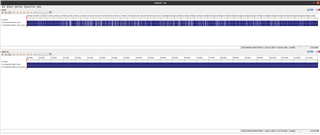
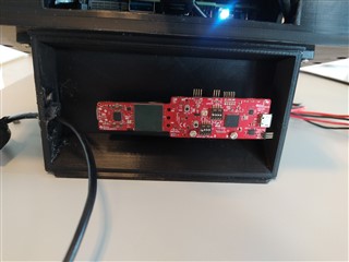
The only difference between these two sets, aside from run time, is the mounting configuration. The top data set was mounted in a 3d printed case of sorts on a pair of standoffs:

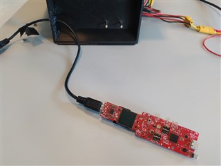
Whereas the lower data set was captured with the sensor sitting on top of the table, "exposed" to ambient environment


Is it likely this is a heating issue? How should we approach this sampling inconsistency?

  • Hi,

    How long were these captures running for in each scenario? How long did it take for the errors to begin? The AOP device does require some thought go into thermal management (as documented here) but I imagine this would take quite a while before any issue would potentially occur.

    Best Regards,
    Alec

  • Hi,

    If you look in the first image you can see the timestamps at the top, the first instance of dropped messages happens after approx 30s.

    Given I'm using the EVM I figured this would be fine as is, in the document you link to figure 11 shows that even without the heatsink I should be below the max temperature.

    So should all be fine as is right?

  • Hello Morten Nissov,

       It may not be due to temperature (Max temperature limit is 105 Deg C), It would unlikely attaining that high temperature.

    It could be due to UART max data rate limit as well, Depending upon duty cycle & detection of number points data points sent by the radar could be chocking the UART max data rate supported. If there are too many reflections number of points detected may go higher and could limit capacity of data transfer and data packets may get dropped. 

    You could reduce the duty cycle or detection threshold to reduce the number of reflections so that point cloud density could get reduced and hence data rate that UART can handle get reduced, then it could improve the package drop rates. 

    Thanks and regards,

    CHETHAN KUMAR Y.B.  

  • Hi,

    Is there a way to monitor packet sizes and verify this is the cause?

    I agree that it reaching 105 deg C seems unlikely, but I tried gathering data from the mount again, this time with an external fan and this time the data seemed much more consistent.

    That being said the heatsink is also quite, uncomfortably so, hot to the touch.

    Edit: Note this is a milder case of dropped messages. We have also experience several instances where the radar will drop messages for 10s of seconds at a time or entirely crash during the run without printing anything to ros terminal. Closing the node at this point results in "escalating to SIGTERM"

    Edit2: Checked duty cycle out of curiosity, I used the demo visuilizer to make the config so I figured everything should be okay. ROS driver outputs:


    Correct me if I'm wrong, but this should mean that my duty cycle is 16%? Since duty cycle = (128 chirps * 130us) / (100ms)

    Edit 3: Just for the sake of it, here is the config file I've been using:

    % ***************************************************************
    % Created for SDK ver:03.05
    % Created using Visualizer ver:3.5.0.0
    % Frequency:60
    % Platform:xWR68xx_AOP
    % Scene Classifier:best_vel_res
    % Azimuth Resolution(deg):30 + 30
    % Range Resolution(m):0.214
    % Maximum unambiguous Range(m):10.95
    % Maximum Radial Velocity(m/s):3.84
    % Radial velocity resolution(m/s):0.06
    % Frame Duration(msec):100
    % RF calibration data:None
    % Range Detection Threshold (dB):15
    % Doppler Detection Threshold (dB):15
    % Range Peak Grouping:disabled
    % Doppler Peak Grouping:disabled
    % Static clutter removal:disabled
    % Angle of Arrival FoV: Full FoV
    % Range FoV: Full FoV
    % Doppler FoV: Full FoV
    % ***************************************************************
    sensorStop
    flushCfg
    dfeDataOutputMode 1
    channelCfg 15 7 0
    adcCfg 2 1
    adcbufCfg -1 0 1 1 1
    profileCfg 0 60 115 7 15 0 0 100 1 64 9142 0 0 158
    chirpCfg 0 0 0 0 0 0 0 1
    chirpCfg 1 1 0 0 0 0 0 2
    chirpCfg 2 2 0 0 0 0 0 4
    frameCfg 0 2 128 0 100 1 0
    lowPower 0 0
    guiMonitor -1 1 1 0 0 0 1
    cfarCfg -1 0 2 8 4 3 0 15 0
    cfarCfg -1 1 0 8 4 4 1 15 0
    multiObjBeamForming -1 1 0.5
    clutterRemoval -1 0
    calibDcRangeSig -1 0 -5 8 256
    extendedMaxVelocity -1 0
    lvdsStreamCfg -1 0 0 0
    compRangeBiasAndRxChanPhase 0.0 1 0 -1 0 1 0 -1 0 1 0 -1 0 1 0 -1 0 1 0 -1 0 1 0 -1 0
    measureRangeBiasAndRxChanPhase 0 1.5 0.2
    CQRxSatMonitor 0 3 4 19 0
    CQSigImgMonitor 0 31 4
    analogMonitor 0 0
    aoaFovCfg -1 -90 90 -90 90
    cfarFovCfg -1 0 0 10.97
    cfarFovCfg -1 1 -3.2 3.20
    calibData 0 0 0
    sensorStart
    

  • Hi,

       You could try reducing the frame rate to see if that helps. 

    Also to reduce the over all power consumption you could explore incorporating low power modes 

    https://dev.ti.com/tirex/explore/node?node=ALNwx9A2x.o5T7wR85tZlQ__VLyFKFf__LATEST

    More details about the low power modes is given in the below app-note.

    https://www.ti.com/lit/an/swra689/swra689.pdf

    Thanks and regards,

    CHETHAN KUMAR Y.B.

  • I just don't really understand what could be wrong here? It seems like heat is the problem, but it just seems weird given that I should be well within the operating envelope of the sensor.

    If it's rated up to 50% duty cycle especially I've tried to add an additional heatsink on the back of the standard one. I just have a hard time seeing how I can run  16% duty cycle, with an extra heatsink and still somehow experience heat issues on a unit that should be fine up to 50% duty cycle with the standard heatsink.

    Is there anything we can do to check this further? Considering how conservative the configuration already is I figure it should work in the present state. How would you recommend I go about verifying the source of the problem?

  • Hello Morten, 

    Quick question: You are using the same EVM in and outside the 3D Printed case?

    Thanks,

    -Shareef

  • Yes, I just take the same unit in and out of the 3d printed mount.

  • I would recommend the following action item:

    Operate the device in low power mode to see if the issue persists. If the issue persists, it would be very likely that, within the case, there are too many reflections number of points detected may go higher and could limit capacity of data transfer and data packets may get dropped, as Chethan suggested.

    Hope this helps.

    -Shareef 

  • Are there any performance drawbacks to low power mode?

    Regarding number reflections, is there a theoretical limit depending on the config? Is there a way to monitor the data transfer? Is there a way to limit the sensor in number of reflections?

    Furthermore, is there some resource from TI that addresses anything related to the previous questions?

  • Another question, this data transfer capacity limit. Is this on the radar or due to the computer it's connected to?

  • Hello,
    For the low power mode, please see the below App Note. You will find all the info you need on AoP and Non AoP devices:
    Below you could find the low power demo code applied to out of box demo framework
     
    For the data transfer rate, that would be limited by UART baud rate that has been set. It is possible depending upon object list and corresponding data (range, doppler, angle) in some configuration may exceed UART max limit and can cause packet drops.
    Hope this helps,
    -Shareef
  • Thanks!

    Regarding data rate, I've set the following parameter in the launch file

    <param name="data_rate" value="921600" />

    so I guess it's at the maximum baud rate? Maybe the out of box demo or the ros driver is publishing unnecessary information?

    I've seen some work in the field which lists a "max scan size", e.g. 256 objects in https://link.springer.com/article/10.1134/S2075108721040039. Could it be relevant to calculate or consider this?

  • Hello Morten,

    Lets take this issue offline. I am going to send you an email regarding this.

    Thanks.

    -Shareef