


Other Parts Discussed in Thread: FDC1004,
Hi Team,
Can you have a look at the following customer question please?
It is about Capacitive Sense. We shall try to detect the presence of liquid in a small reservoir with a capacitive sensor. For this we look at the Ti devices FDC1004 and FDC2214.
According to our idea, a sensor surface in the finger pattern is a suitable shape for our application.
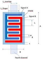
But now, after researching the datasheets, it is not quite clear to us how the two sensor surfaces should be wired. For a singel-ended measurement, we probably have to put one surface on ground.
For a differential measurement, CIN1 and CIN2 are connected to the two sensor surfaces and Shild is connected to SHLD1. The whole thing probably works with the FDC1004. Is such a connection also possible at the FDC2214? Is it simply INxA and INxB there? For the Shild signal is then still an external operational amplifier necessary, which uses the INxA Signal? Is there also an application note for this?
Thank you,
Franz
