Other Parts Discussed in Thread: USB2ANY
Hello,
I have a TMP 117EVM and I want to use a dual sensor configuration. I have some sensors that are made at our company that are attached to a flex pcb. I've actually already asked this question here:
This is the schematic we have:
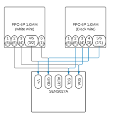
and this is what it looks like:
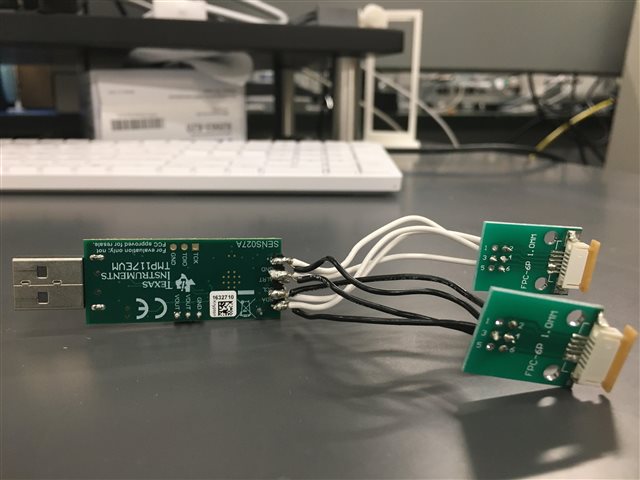
(notice that the instead of connecting 5 to voltage and ground using the through holes, we are using a bit of solder on the connector/clamp [white and beige in picture) to jump 4 and 5 together on 1 fpc and 5 and 6 on the other)
This configuration works and is capable of reading data with the sensors we have. However having both the black and white wire soldered to one male pin header makes it weak and precarious and prone to breaking off (as has happened already)
So we decided to run it through a circuit board, allowing for neater soldering (theoretically) and potential for easy rewiring if necessary. See below for what that looks like:c
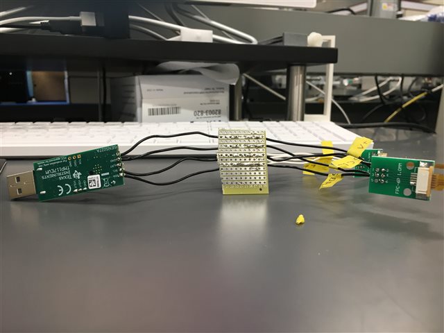
You can assume that each through hole on the FPC is connected to the correct through hole on the temp sensor chip (as seen in the schematic at the the top of this post). From the wiring perspective it should be exactly the same as the functioning circuit mentioned earlier. Using the same sensors however, I get an error using the dual sensor gui:

I've used a multimeter to check that all the connections are working, and it still doesn't work. Any ideas?