This thread has been locked.

If you have a related question, please click the "Ask a related question" button in the top right corner. The newly created question will be automatically linked to this question.

LDC2114EVM: Signal from INTB does not change

Part Number: LDC2114EVM
Other Parts Discussed in Thread: LDC2114

Hello,

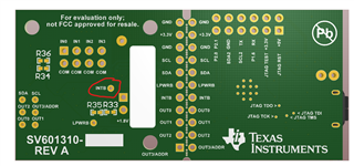
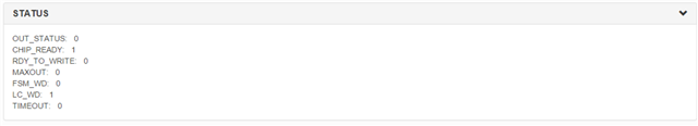
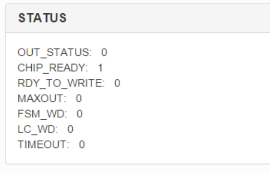
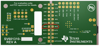
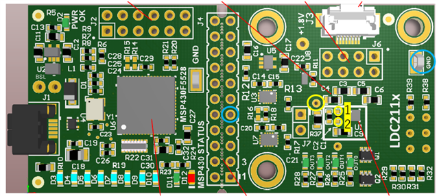
When I was using LDC2114EVM, I found that D11 or D12 turned red. Then, I disconnected USB cable and connected it again. After that, signal from INTB does not change, though it should decrease when sensors are detecting metal. What should I do in order to fix it?

Best regards,

  • Hello, 

    I have a couple debugging questions for you in regards to this. 

    • Did you perform a firmware update with the EVM or are you still using the firmware that came on the board? 
    • If you probe the INTB testpoint on the board, are you seeing the INTB signal change? 

    Thank you, 

    Justin Beigel

  • Hello,

    ・When the problem occurred, I was using the firmware that came on board. Then I performed a firmware update to EVM_LDC2114_(D3_D10_prox) to see if LDC2114EVM works normally again.
    ・If I probe the INTB, I can see 1.8V but it does not change no matter what I do.

    Best regards,

  • Hello, 

    Thank you for the clarification. I have a few follow up tests for this: 

    • Are the OUTx pins changing values as expected? 
    • If you watch the Data registers, are they changing with the metal target interaction? 
    • If you change the polarity of INTB (using INTPOL bit 2), does the pin voltage change? 

    Lastly, can you provide the register configuration that you are using for this board? 

    Thank you, 

    Justin Beigel

  • Hello,

    Thank you for your reply. 
    ・OUTx pings are working properly.
    ・ Are these Data registers? If they are, I think they are changing. Upper is when there is no metal interaction. Bottom is when there is metal interaction. 


    ・I do not know how to change the polarity of INTB. How can I do that?

    I am not sure what register configuration is, but are these what you want to see?


    Best regards,

  • Hello, 

    Yes those are the data registers. You can also view them using the Data Streaming tab of the GUI. 

    You can change the polarity of INTB by using the Interrupt Polarity section of the configuration page. Be sure to put the device in configuration mode before changing any register settings. 

    Those screenshots give me enough information for the register configuration but you can also view then using the registers tab of the GUI. 

    It looks like the LC_WD flag is set in the STATUS register, this will also cause the INTB pin to trigger and would be a reason the pin would seem "stuck" if the error is never resolved. Do you have a sensor connected to each channel? If not, can you disable any channels without a sensor connected and check the status register again to make sure the LC_WD flag is cleared. 

    Best Regards, 
    Justin Beigel

  • Hello,

    I am glad that the data I showed you was what you wanted to see.

    I changed polarity to active low. However, INTB was always 1.8V even when sensor is active. I am using this sensor bellow with attached cable. So, this sensor is connected to each channel. I checked the status to find that LC_WD was 0.

    Best regards,

  • Hello, 

    Thank you for the information. Can you try two other tests for this: 

    • Check the signal at the INTB jumper between the MCU and IC portions of the board: 
    • Measure the resistance between the INTB pin and Vdd to see if there is somehow a short on the board 

    Thank you, 

    Justin Beigel

  • Hello,

    I checked the signal between blue circle. It always showed about 3.1V even when a sensor is active. In order to measure resistance between the INTB pin and Vdd, I measured resistance between yellow circle. Circle 1 showed 9.2Ω, and circle 2 showed 33.6Ω respectively.  Did I measure them correctly?

    Best regards, 

  • Hello, 

    Your measurements were at good points but they seem a bit low. Was this measured while the board was on or off? 

    Also, to clarify, the only issue is that INTB is not signaling properly, correct? The EVM works normally for all other purposes? 

    Thank you, 

    Justin Beigel

  • Hello,

    When blue circle was measured, board was on. When yellow circle was measured, board was off.

    In my purpose, I use only INTB signal. Blue LED turns on properly if sensors are active. So, I think only issue is INTB signal. 

    Best regards,

  • Hello, 

    It seems like something is shorted on your board for the INTB pin. The resistances should not be that low when the board is powered down. If you need the INTB functionality back, you will have to get a new board or find the source of the short and fix it. 

    If you only need to monitor the button states with INTB, you can use the digital output test points on the board or view the D3-D6 diodes with the most recent firmware: 

    Best Regards, 

    Justin Beigel

  • Hello,

    I understand that something shorted out. I will buy a new one. Thank you for your kindness.

    Best regards,