This thread has been locked.

If you have a related question, please click the "Ask a related question" button in the top right corner. The newly created question will be automatically linked to this question.

TMAG5170-Q1: Temperature drift

Part Number: TMAG5170-Q1
Other Parts Discussed in Thread: TMAG5170

Dear Sir, Madam,

I recently asked you more details about the temperature drift of the TMAG5170 but I need more help to understand correctly this parameter.

I saw on the datasheet the temperature drift is worth maximum 2,8% between 25°C and 125°C and maximum 4,3% between -40°C and 25°C. I don't understand what does this percentage represents.

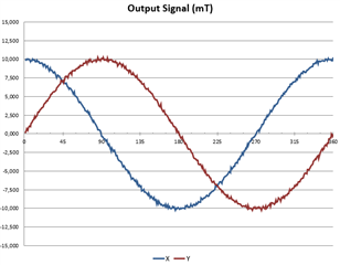
For example, the sensor works at 25°C with an input range of 25mT, it is supplied in 5V, the maximum magnetic field measured is about 10mT (see the curve below).

In theory, if the systems works at -40°C, what do we have to do with the temperature drift of 4,3% :

- Do we have to add 4,3% of 10mT (so 0,43mT) to all magnetic fields measured ?

- Do we have to add 4,3% of 25mT (so 1,075mT) to all magnetic fields measured ?

- Do we have to add 4,3% of the measured value for each value (for example at 45° both magnetic fields are worth about 7,5mT so we add 7,5*4,3% = 0,3225mT ; at 30° the magnetic field in Y is worth about 5mT so we add 5*4,3% = 0,215mT, and it is worth about 8mT in X so we add 8*4,3% = 0,344mT ; ...) ?

- Is there an other thing ?

Best regards.

Arnaud

  • Arnaud,

    Thank you for reaching out again.  I have copied the relevant specification items from the datasheet as a reference.  Sensitivity is similar to the gain of an amplifier, and would most fittingly apply to the bit weight shown at the beginning of the magnetic characteristic portion of the spec table.

    As a result, you can apply the calculation directly to the output code as a reference for the possible range of error. 

    For instance, a sensor set to the +/- 50 mT range and detecting 45 mT at 25C could have the result vary +/- 1.26 mT (+/-2.8%) at 125C, or by +/- 1.935 mT (+/-4.3%) at -40C. 

    In the event that the input is near the full scale value, and the drift would cause it to exceed the maximum, the result would appear as a fully saturated output code.

    When considering the impact of such a drift on the system performance, it is also important to consider the drift of any other axis used to perform position calculations.  For example, the angle output relies on the CORDIC function which calculates the arctangent of any two outputs.  This ideally requires that the two outputs have the same amplitude to provide a circular reference.  Amplitude mismatch will result in non-linearity.  Supposing both channels experienced identical output drift, this would result in no error.  We must therefore also consider the sensitivity mismatch drift which is specified here:

    In the case of the 25C to 125C drift, it is not possible to have one output drift by +4.3% and the other drift by -4.3%.  In the event that the first output were at the maximum 4.3% drift, then the second output should experience no lower than 0.3% drift (4% less than the first channel).

    Thanks,

    Scott