


Other Parts Discussed in Thread: LP87524P-Q1,
Hi
I'd like to know LC Filter design on AWR2243's VIN_13RF1/2 with LP87524P-Q1.
There seems to be a difference between the specification sheet and the development board design policy.
Could you tell me following question one by one for me?
①Any recommendations for L and C constants on the output voltage line?
According to the specifications below, L is 470uH, Cout is 22uF, and Cpol is 100uF or less.
https://www.ti.com/lit/ds/symlink/lp87524p-q1.pdf?ts=1662353734239&ref_url=https%253A%252F%252Fwww.ti.com%252Fproduct%252Fja-jp%252FLP87524P-Q1

However, in the development board schematic, it looks like L is 470uH, Cout is 22uF +22uF, and Cpol is missing.
https://www.ti.com/tool/ja-jp/MMWCAS-RF-EVM#tech-docs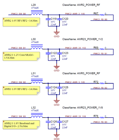
②Any recommendations for L and C constants of filter on the input voltage line for VIN_13RF1/2 ?
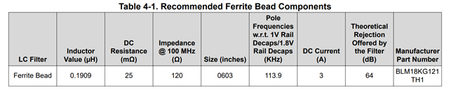
The specifications below recommend ferrite beads.
https://www.ti.com/jp/lit/an/swra577a/swra577a.pdf?ts=1662340113089&ref_url=https%253A%252F%252Fwww.ti.com%252Ftool%252Fja-jp%252FLP87524Q1EVM

However, the schematic for the development board looks like it has an LC filter on it.
https://www.ti.com/tool/ja-jp/MMWCAS-RF-EVM#tech-docs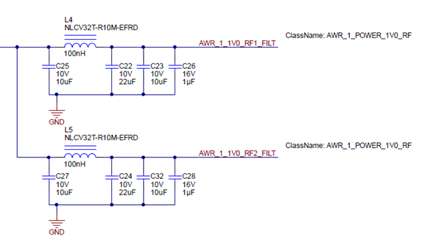
③How to determine the design frequency of an LC filter on the input voltage line for VIN_13RF1/2 ?
In the document below, it looks like you are designing a 100-200KHz ferrite bead while paying attention to the noise after signal processing.
What is 113.9KHz?(Pole Frequencies w.r.t. 1V Rail Decaps/1.8V Rail Decaps (KHz) )
https://www.ti.com/jp/lit/an/swra577a/swra577a.pdf?ts=1662340113089&ref_url=https%253A%252F%252Fwww.ti.com%252Ftool%252Fja-jp%252FLP87524Q1EVM
Thanks
