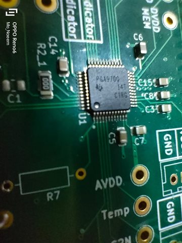
Hello , I designed and manufactured PCBs featuring PGA970 , I have 4 boards , 2 of them were programmed and working perfectly using CCS version 10.0.1 and compiler V5.2.8.
I configured the Target configuration exactly as the software quick guide of the PGA970 , and I Ran Integration test before launching the configuration file and It succeeded as follows :
_____________________________________________________________________________________________________________________________________
[Start: Texas Instruments XDS2xx USB Debug Probe_0]
Execute the command:
%ccs_base%/common/uscif/dbgjtag -f %boarddatafile% -rv -o -S integrity
[Result]
-----[Print the board config pathname(s)]------------------------------------
C:\Users\A5EE6~1.WAE\AppData\Local\TEXASI~1\
CCS\ccs1010\0\0\BrdDat\testBoard.dat
-----[Print the reset-command software log-file]-----------------------------
This utility has selected a 560/2xx-class product.
This utility will load the program 'xds2xxu.out'.
The library build date was 'May 7 2020'.
The library build time was '20:23:44'.
The library package version is '9.2.0.00002'.
The library component version is '35.35.0.0'.
The controller does not use a programmable FPGA.
The controller has a version number of '13' (0x0000000d).
The controller has an insertion length of '0' (0x00000000).
This utility will attempt to reset the controller to enter SWD mode.
-----[Print the reset-command hardware log-file]-----------------------------
This emulator does not create a reset log-file.
-----[Perform the SWD Mode Integrity test]-----------------------------------
This test will read the IDCODE register 1 time.
The IDCODE register value is 0x0bb11477.
The SWD Mode Integrity test has succeeded.
[End: Texas Instruments XDS2xx USB Debug Probe_0]
_____________________________________________________________________________________________________________________________________
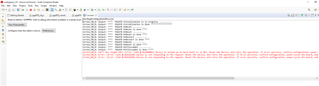
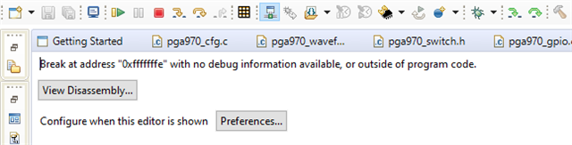
When I program the other 2 using the same code a target configuration file with the same configurations I get the following

but I don't get the green resume symbol which allows me to resume the run and therefore the GPIO doesn't light and I don't get any outputwaveforms as if the IC hasn't been programmed.
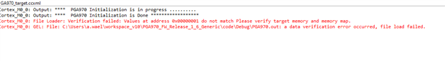
so I disconnected the Programmer and connected it again , and tried again to launch the configuration file and connect to target , this time I get the following error
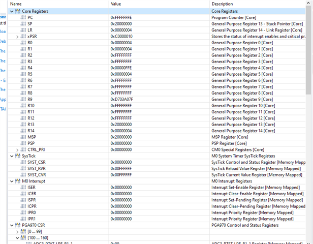
I am sure that the IC isn't damaged , since it's regulators are all functioning properly : Analog and Digital & also I can read the registers of the IC using CCS
but something is going wrong making me can't program these two boards although I am using exactly same PCB design and the same code, do you know any reasons behind these errors ? I tried reaching the pdf for Data verification but I receive this site is under maintenance error.
This is what i receive when I connect target
These are my Program/Memory Settings
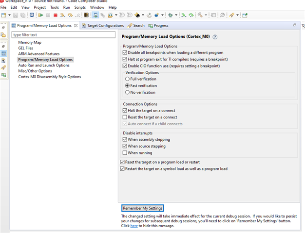
These are my Autorun settings

I tried measuring the voltage on the reset pin it's 2.7V
What might be the problem , please?
Thank you very much in advance,
Amr Wael