


Hi all
We are using the TMCS1101A2U in our design to measure a switchable current of around 7A. The current sensor is supplied with 3.3V and therefore the idle output voltage is 0.33V, when no current is flowing through the sensor. Recently, we made a change to the switching circuit of the load, but no changes to the TMCS1101 circuit. Now we see random spikes on the output of the current sensor for a duration of up to 3s, even though no current is flowing (we monitor the battery output current and an increase of 7A would be clearly visible). Our schematic is posted below.
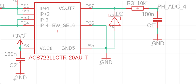
We use six of these sensors in parallel, they are all connected to the same supply voltage.
D2 is a 1.8V zener diode to limit the output voltage to 1.8V for the ADC. The ACS722LLCTR-20A-T in the image is replaced by the TMCS1101A2U, we haven't update the schematic yet. But neglecting the different voltage output per amp, they are basically interchangeable. The load current flows into the IP+ pins.
The layout looks like this. The plane under U1 (TMCS) is GND. The layout is pretty much the same for all TMCS1101.
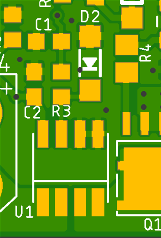
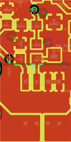
There are no current spikes going to the GND plane under the IC, while the output spikes occur. I'm aware, that we didn't fully incorporate the recommended PCB design from the datasheet.
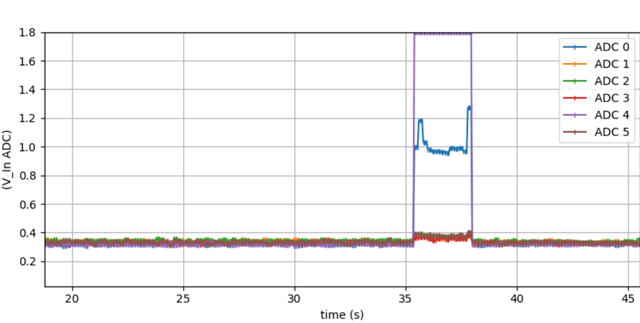
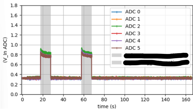
The weird behavior looks as follows.
Note that the zener diode clamps the max voltage output level to 1.8V. The TMCS1101 indicates a current of almost 15A (0.1*3.3V + 100mV/Amp -> around 15A), but this would have caused the 10A Fuse in front of the load to blow.
Interestingly, the system functioned perfectly on a second try. As you can see, all 6 TMCS1101 measured the current as expected and the circuitry (fuses) around it are fine as well.
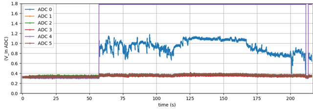
After a new try, it got even worse than on the first try. The TMCS1011 on ADC 4 suggests a current of 15A flowing for the whole time, but no current was flowing.
Conclusion:
If there was a problem with the supply voltage, all TMCS would see this on their outputs, but they don't. Therefore, i think this is not the cause of the problem. Interestingly, all other ADCs measure a slightly higher voltage while the two (ADC 0 and ADC 4) channels are seeing high values.
From the circuitry shown at the top, the signals go directly on to Beagle Bone Black ADC input pins, with no additional components in between. Do you have any idea what is causing this weird behavior, which in addition appears very randomly? Can this output on even be possible from the TMCS, when no current is flowing? Note, that this system has been running smoothly with the ADC for years.
Thanks in Advance and KR
Daniel
