This thread has been locked.

If you have a related question, please click the "Ask a related question" button in the top right corner. The newly created question will be automatically linked to this question.

TMAG5273: TMAG5273A1QDBVR

Part Number: TMAG5273
Other Parts Discussed in Thread: DRV5013, DRV5011

Hi

As I am using the magnetic sensor TMAG5273A1QDBVR for measuring the rpm of the motor and I was going through the datasheet and I was not able to find the bandwidth of the sensor so that I can use it. So can you help me out with it. And can you help me out by sending application notes regarding it and for the rpm of motor using magnetic sensor.

Regards

Nirmith 

  • Hello Nirmith,

    Thanks for posting to the sensing forum! Is there a specific reason why TMAG5273 was chosen for measuring the RPM of a motor? Typically, for RPM measurements digital hall latches or switches are used. As the motor rotates you will obtain a square wave, obtaining the electrical frequency of the motor lets you mathematically convert the electrical frequency to the motors RPM. I am just curious if the plan is to use the alert pin on the TMAG5273 in order to make the measurement or if another method was going to be used.

    The frequency bandwidth of TMAG5273 isn't specifically published because it mainly depends on your setup of the device. You can see the spec under section 6.11 Power up and Conversion Time. If only one channel is enabled then the conversion time is 50us then 20kHz, but once other channels are added then conversion for each subsequent channel is 25us.

    I hope this helps!

    Best,

    Isaac

  • Hi Isaac 

    Thank you for giving me an update on it. So can you suggest me with a latch or switch.

    Regards 

    Nirmith

  • Hi Isaac

    And its sensing range should be +/- 600 G.

    Regards 

    Nirmith

  • Hi Isaac

    As we are interfacing it with I2C with the microcontroller. As the I have searched it on the net that frequency of the sensor is used for measuring the RPM of the motor. So the device will be mounted on the industrial motor and it get the data and sends to the microcontroller.

    Regards 

    Nirmith

  • Hey Nirmith,

    Thanks for the info. My suggestions would be to go with a latch, either DRV5011 (smaller package in case it makes your design easier) or DRV5013. If you are getting about +/-60mT from the permanent magnets on the motor then you shouldn't have any problems finding a sensitivity suitable for your motor.

    When using the electrical frequency from a digital latch you can use the following formula to calculate the RPM of the motor: 

    RPM= (60*Electrical frequency)/pole pairs

    Electrical frequency being the measured frequency from your latch, and pole pairs is the amount of pole pairs in the rotor.

    Best,

    Isaac

  • Hi Isaac 

    I need 3 axis x,y and z but the latch is just one axis.

    Can you suggest me out a part for it so that I can use to measure RPM of the motor.

    Regards

    Nirmith

  • Hello Nirmith,

    Are you using a single axis to measure the RPM of the motor and the other channels for something else? If so can you specify what you are doing with the other two channels?

    Best,

    Isaac

  • Hi Isaac 

    As we are designing a product which can be mounted on an motor as the motor and the product can be mounted on perpendicular or top of the metal surface or diagonally on the motor so my client has specifically suggested to use 3 axis sensor. 

    Regards

    Nirmith

  • Hello Nirmith,

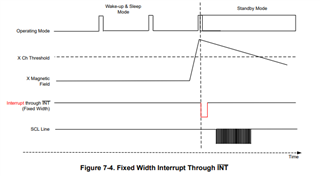
    It sounds like you are using the best option for your application at the moment. Another option you can do is have TMAG5273 set up to generate an interrupt INT pin when the threshold has crossed a specific value. This will generate the square wave that is typically used to obtain the electrical frequency. Look at section 7.3.3 in the datasheet for more information on how the interrupt functions works. The formula would change slightly since you would be getting twice the amount of transitions since it would function as a switch.

    Best,

    Isaac

  • Hi Isaac 

    Can you give me a more specific explanation on this quote "TMAG5273 set up to generate an interrupt INT pin when the threshold has crossed a specific value". And can you share me with code so that it can interface with microcontroller with I2C and the formula for it.

    Regards

    Nirmith 

  • Hey Nirmith,

    When INT_MODE is set on the TMAG5273, it can be setup to create an interrupt either on the SCL pin or through the INT pin. I find it easier to interrupt through the INT pin but this also depends on how many GPIO's you have available on your MCU.

    The interrupt occurs when the magnetic field goes above your programmed threshold, this is what I mean by a specific value. The threshold value is chosen by you and is configured using the X_THR_CONFIG, Y_THR_CONFIG, or Z_THR_CONFIG registers. The direction you choose mainly depends on where you are sensing the rotors polarity transitions. Essentially, you would be setting up TMAG5273 to act as a switch.

    If you choose to go through the interrupt function, then it might not be completely necessary to read the magnetic data for that channel since you should be seeing the INT pin toggling when the motor is running. The INT pin would be connected to a microcontrollers GPIO pin where you can use a timer to time the frequency of the falling edges of the input (falling edges since this is an active low pin).

    I made a mistake earlier and the calculation for RPM would remain the same, RPM= (60*Electrical frequency)/pole pairs. Since we are only timing the edges it would not make a difference to the formula. This would all be done inside the MCU. Just keep in mind that you still have to pay attention to the conversion time and we recommend that the conversion time is more than 2 times the max RPM you are expecting from the motor.

    As far as code goes I am not sure if I have anything to provide. Did you just need code to configure the TMAG5273 into the interrupt mode? Or were you looking for something else?

    Best,

    Isaac

  • Hi Isaac 

    I mean the code which is used to configure the sensor with the MCU and to configure the interrupt also. Or can you send me sample codes related to this TMAG5273 so it will be easy to understand.

    Regards

    Nirmith

  • Hey Nirmith,

    We are currently working on creating sample code for this device. If you send me a private message I might be able to share some of the parts you may need to configure the thresholds and the interrupt on the sensor.

    Best,

    Isaac

  • Hi Isaac 

    Where I can send you a private message.

    Regards 

    Nirmith

  • I just sent over a friend request, if you accept you should be able to hover over my name and get the option to send a direct message.

    Best,

    Isaac

  • Hi Isaac 

    I have accepted your request

    Regards

    Nirmith

  • Hello Nirmith,

    I will close this thread now, thank you!

    Best,

    Isaac

  • Hi Isaac 

    Ya sure Thank you for helping me out.

    Regards 

    Nirmith