f the voltage of REF terminal is between 2.5v to 5V(VDD), how this IC's output would behave?
Isn't that inconsistent with Vref being 0-2.5V?
If so I like to develop a circuit which can measure -90A to +90A by using inverting opamp circuit.
This thread has been locked.
If you have a related question, please click the "Ask a related question" button in the top right corner. The newly created question will be automatically linked to this question.
f the voltage of REF terminal is between 2.5v to 5V(VDD), how this IC's output would behave?
Isn't that inconsistent with Vref being 0-2.5V?
If so I like to develop a circuit which can measure -90A to +90A by using inverting opamp circuit.
MASAO,
The only potential topology you could theoretically perform here to increase the current would be to place multiple devices in parallel. This theoretically should allow the current to increase, as multiple devices would share the load current. However, we have not developed any collateral to such a use case.
I didn't mean to increase the current range at all.
I want to know if below circuit works or not.

Masao,
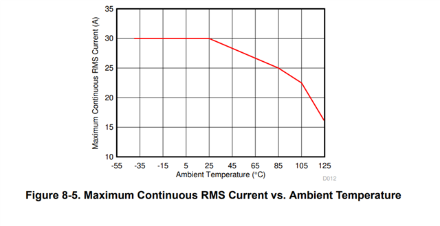
Apologies. I saw the 90A and thought this was an expansion problem. That said, this will be an issue here, as the device is not typically able to handle this amount of current, unless it is duty cycled. Are you looking to measure pulses of current here, or is the +/- 90A a continuous magnitude? Here is the curve for maximum continuous current:

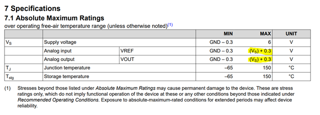
Regarding the circuit, am I understanding correctly that you are attempting to cast the 0-->5V output range of the TMCS1100 to a +/-15V output range here? The challenge I see here is that there is potential for the feedback loop to drive either the VOUT or REF pin greater than 5V (especially the REF pin being directly tied to the output of the amplifier. As you can see from the abs max table below, neither of these pins may be driven more than 300mV above the supply voltage, or they may be subject to damage:

I would choose a suitable op amp and run a few simulations over various use cases to verify that this does not happen in the circuit.
Calolus,
Thank you very much for your answers.
As for the OPAmp issue.
I see a point. I will use a single OpAmp with 0-5V power for the first one.
As for the 90A issue.
Expected load condition is 60A 5 seconds per 30 seconds followed by -60A 5 seconds per another 30 seconds.
I will apply heatsink on the device. By the way, the 90A came from the VREF terminal is set to 0V.
As for the case of setting VREF terminal to VCC level.
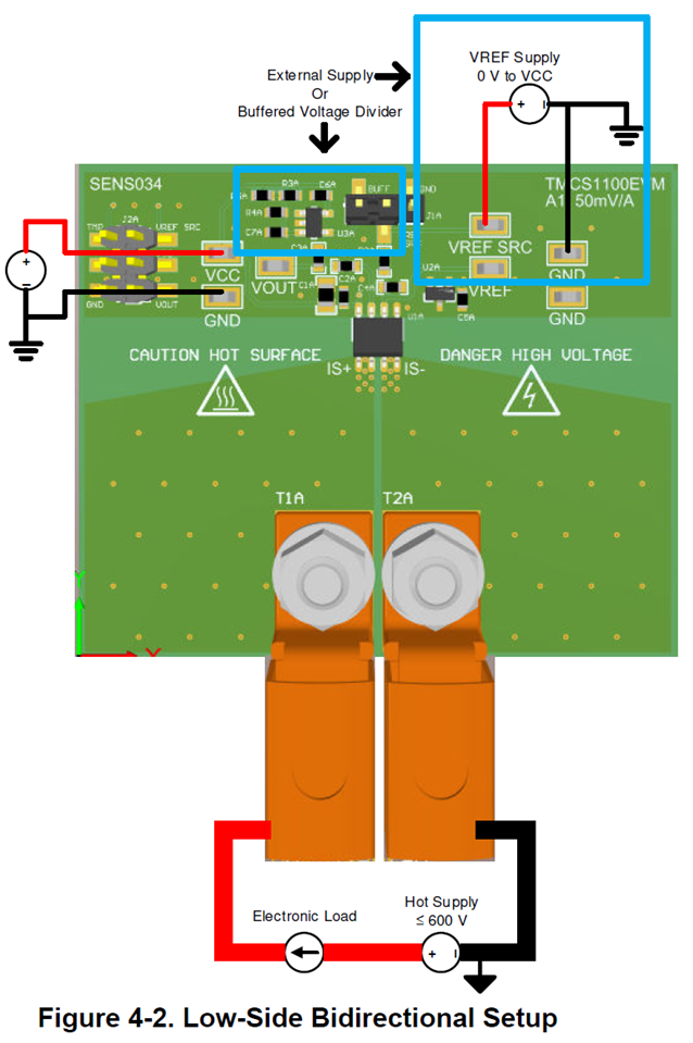
The User Manual for TMCS1100 EVM suggested to apply 0V to VCC on VREF terminal.
