This thread has been locked.

If you have a related question, please click the "Ask a related question" button in the top right corner. The newly created question will be automatically linked to this question.

[FAQ] How would you be able to add backlighting or illumination to an inductive touch button implemented with LDC3114 or LDC2114?

Other Parts Discussed in Thread: LDC3114-Q1, LDC2114, LDC2112, LDC3114

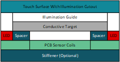
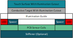
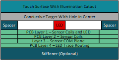
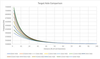
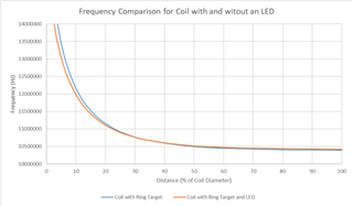
If I need to add illumination or cutouts in the surface of my inductive touch button, what design concerns should I keep in mind?

  • For basic information on inductive touch buttons please see the How to get started with Inductive Touch Buttons E2E FAQ.


    Having an illuminated inductive touch button is similar to a normal touch button but has a couple different considerations that should be kept in mind. Having an LED next to the sensor coil in a PCB layout does not impact the button performance significantly when the target surface is close to the sensor coil. For button applications, we recommend keeping the target distance below 20% of the coil diameter already so there isn't much concern for the LED impacting the magnetic field generated by the coil. 

    In the case where the outer touch surface is nonconductive, one implementation could be to utilize an illumination guide between the conductive target and the touch surface. The illumination guide could be any material that disperses light well and does not take up a large amount of space. An example of this mechanical stackup would look like this:


    The concern with this implementation would be keeping the target, guide, and touch surface thin enough that there is still deflection in the metal target when pressed. Thicker and stiffer layers will require more force on the button surface for a press event to be detected. Devices like the LDC2112, LDC2114, LDC3114, and LDC3114-Q1 have a gain setting included in their button algorithm that can help adjust for a stiffer button but any noise on the sensor is also increased by the gain. One way to keep the target layer thin is to use something like copper or aluminum tape for this layer.


    An alternative approach is to put the illumination guide under the metal target. This requires that the metal target have a cutout for light to shine through.


    This implementation allows for the metal target to be the outer surface but the shape of the cutout could impact the formation of eddy currents on the metal target and therefore degrade the coupling between the target and sensor coils. This is why keeping the cutout small would be important.


    The last implementation I will mention would be to have the LED in the center of the sensor coil. This would require that the inner diameter of the sensor coil is large enough to house the LED and the board has enough layers to route the LED traces under the coil. Preferably, a layer of the COM plane with the LDC2112, LDC2114, LDC3114, and LDC3114-Q1 devices would be in between the coil and traces. For example, in a four layer board, the top two layers would house the LED and sensor coils, the third layer would have the COM plane to shield the coil and the fourth layer would have the traces from the LED as shown in the following stackup:


    In this case, it is important to keep the metal target close so the impact of the LED is minimal to the target and sensor coil coupling. Since the eddy currents form in a ring on the metal target, putting a hole in the center will still allow for the eddy currents to form as long as the hole isn't made too large compared to the coil size. To emphasize this point, the following image shows the simulated eddy currents formed on a square target above a circular sensor coil:


    Simulating the frequency of the sensor coil while varying the target distance gives an idea of the change in frequency expected from the target interaction with the coil. From there, a hole is introduced into the square target and varied in size to create the family of curves shown in the below plot. These simulations were done using a 6mm 4 layer coil.


    As the hole size increases, the change in frequency from the target interaction decreases. Because of this, keeping the hole smaller is important to get the best results from the sensor and target interaction.


    To further look at the impact of adding an LED into the electromagnetic simulation, here is a comparison of a coil with and without an LED added to the middle of the coil. The simulation uses a 2 layer coil with the LED in the center and the traces to the LED dropping down to the 4th layer of the PCB.


    This graph shows that there is minimal impact from the metal in the LED to the electromechanical coupling between the inductive sensor coil and the metal target. These results are an ideal scenario and do not account for any noise or switching frequencies on the LED traces.

    Best Regards, 

    Justin Beigel