Other Parts Discussed in Thread: MMWAVEICBOOST,
Hello everyone,
I have a problem with regard to the AWR6843ISK and mmwaveICboost integration.
As the attached photos demonstrates,
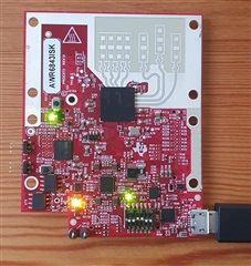
the radar evaluation board in my possession is the AWR6843ISK PROC073 REV D.
The rear of the board looks like this:
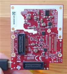
As one can see, the right connector is not present on the PCB in this board version. The right and the left connectors (the left connector is present on the PCB, the right connector is not)
are supposed to enable a communication interface between the AWR6843ISK and the MMwaveICboost board.
If we look at the front of the MMwaveICboost:
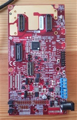
One can see that there are 2 connectors which are supposed to be used as a radar sensor interface, J4 and J17.
Connecting them together means that only the left connector in the photo of the rear-sensor board (taken above), will be
connected to J4 connector at the front-MMwaveICboost photo above.
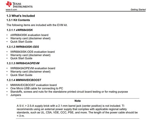
My misunderstanding stems from the fact that I cannot find any mention in the user guide regarding as to how one is supposed to connect the AWR6843ISK REV D to the MMwaveICboost board:
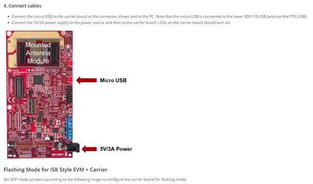
This is how I have connected the board (photo below), I would like to make sure that it is correct in order to prevent any potential frying of components.
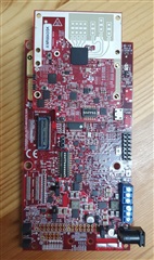
Can anyone here share with me some advice in the matter?
Which Part in the MMwaveICboost user guide will be the best reference as to regarding to how should I continue the integration between the components?
Our aim is to interface the AWR6843ISK to the CC2652 microcontroller through the MMwaveICboost board.
Thank you in advance,
RoadBox Team