Other Parts Discussed in Thread: TMAG5115, TMAG5115EVM
We are designing position sensing circuit for BLDC Motor (Control strategy is Six step commutation), where we are planning to use DRV5013 Hall latch. We are having few queries on that,
- Why magnetic switchs cannot be used instead of the Latches for this Motor control application ? Can you please send any reference design/ application note explaining the use of magnetic switch in Motor control application instead of Latch, if there is any ?.
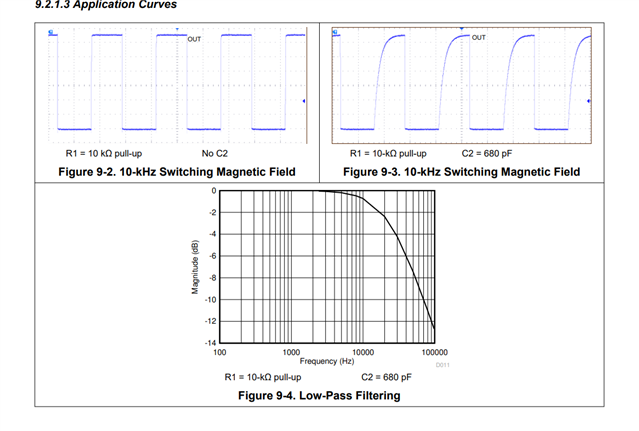
- In DRV5013, apart from the pull up resistor, is it necessary to connect the Capacitor (C2 as per datasheet) if we are already having a single pole first order RC filter deployed on the line ? What purpose do the capacitor C2 serve apart from filtering ?
- What should be the cut off frequency of that RC filter (question-2),as recommended by TI if the required bandwidth of the sensor is 4500Hz ? On What basis the filter cut off frequency is decided ?
- Why this DRV5013, is rated with higher voltage, upto 38V ? For what application it is rated with this high voltage ? For those application, is it recommended to directly bias this with, say 30V ? What are the benefits seen here?