This thread has been locked.

If you have a related question, please click the "Ask a related question" button in the top right corner. The newly created question will be automatically linked to this question.

AWR1642BOOST: How can I modify the rangeBin number from 64 to 128 in project single_row_occupancy_6443?

Part Number: AWR1642BOOST

Hi! TI Team!

Currently we work on the specific project single_row_occupancy_6443 with 6843AOPEVM.

Now we can dump the message and send the radar cfg to the radar use data port and user port, respectively.

We consider using this cfg:

sensorStop
flushCfg
dfeDataOutputMode 1
channelCfg 15 7 0
adcCfg 2 1
adcbufCfg -1 0 1 1 1
profileCfg 0 60.00 205 11 41 0 0 97.0 1 128 2200 0 0 36
chirpCfg 0 0 0 0 0 0 0 1
chirpCfg 1 1 0 0 0 0 0 2
chirpCfg 2 2 0 0 0 0 0 4
frameCfg 0 2 180 0 200 1 0
lowPower 0 0
guiMonitor -1 0 1 0 0 0 0
cfarCfg -1 0 2 8 4 3 0 15 0
cfarCfg -1 1 0 4 2 3 1 15 0
multiObjBeamForming -1 0 0.5
clutterRemoval -1 1
calibDcRangeSig -1 0 -5 8 256
extendedMaxVelocity -1 0
lvdsStreamCfg -1 0 0 0
compRangeBiasAndRxChanPhase 0.0 1 0 1 0 1 0 1 0 1 0 1 0 1 0 1 0 1 0 1 0 1 0 1 0
measureRangeBiasAndRxChanPhase 0 1.5 0.2
CQRxSatMonitor 0 3 4 63 0
CQSigImgMonitor 0 127 4
analogMonitor 0 0
aoaFovCfg -1 -90 90 -90 90
cfarFovCfg -1 0 0.3 2.0
cfarFovCfg -1 1 -1.0 1.00

% Demo Specific Commands
occStateMach 7 20 5 20 3 15 10 3 40
% zone 1 (2nd row driver side) cuboids
cuboidDef 1 1 0.30 0.75 0.3 1.0 0.95 1.3
cuboidDef 1 2 0.30 0.75 0.2 1.0 0.4 0.95
cuboidDef 1 3 0.30 0.75 0.1 1.0 0.0 0.4
% zone 2 (2nd row middle) cuboids
cuboidDef 2 1 -0.10 0.10 0.3 1.0 0.95 1.3
cuboidDef 2 2 -0.10 0.10 0.2 1.0 0.4 0.95
cuboidDef 2 3 -0.10 0.10 0.1 1.0 0.0 0.4
% zone 3 (2nd row passenger side) cuboids
cuboidDef 3 1 -0.75 -0.30 0.3 1.0 0.95 1.3
cuboidDef 3 2 -0.75 -0.30 0.2 1.0 0.4 0.95
cuboidDef 3 3 -0.75 -0.30 0.1 1.0 0.0 0.4
sensorStart

I changed the parameter in profileCfg. But it dump the Error -1. 

How can I fix this problem?

We need the rangeBin number from 64 to 128. 

Is there any help?

Thank you!

Best regards,
Webb

  • Hi Webb,

    A dedicated team member will address this shortly. Thank you for your patience.

    Best,

    Nate

  • Hi Webb,

    What is your goal? Do you wish to effectively double your max range or are you attempting to improve your range resolution?

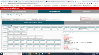
    As for the error you are seeing, you have increased the number of ADC samples. When doing this, there are some considerations that must be taken for the configuration to be valid. For example, you must ensure that the ADC start time and ramp time are sufficient to capture that number of samples at the desired sampling rate. The advanced tab of the Sensing Estimator tool can help you modify parameters and will give warnings or errors if you exceed a certain restriction. 

    Best Regards,

    Kevin

  • Hi! Kevin Ortiz!

    Thank you for your reply.

    I've used this tool from the basic to the chirp design. 

    After the basic, tool dump this cfg:

    ========== Successfully sent to ADVANCED ==========

    % ===============================================================================
    % NOTE: Profile config and frame config provided below are not guaranteed to work
    % with mmWaveBasic SDK without calibrating digital processing chain.
    % ===============================================================================
    profileCfg 0 60 5 6.4 291.07 0 0 5.26 1 851 3000 0 0 30
    channelCfg 15 7 0
    adcbufCfg -1 0 1 1 1
    chirpCfg 0 0 0 0 0 0 0 1
    chirpCfg 1 1 0 0 0 0 0 2
    chirpCfg 2 2 0 0 0 0 0 4
    frameCfg 0 2 1 0 1 1 0

    After chirp design, tool dump this cfg:

    sensorStop
    flushCfg
    dfeDataOutputMode 1
    channelCfg 15 7 0
    adcCfg 2 1
    adcbufCfg -1 0 1 1 1
    profileCfg 0 60 5 6.4 291.07 0 0 36 1 128 3000 0 0 30
    chirpCfg 0 0 0 0 0 0 0 1
    chirpCfg 1 1 0 0 0 0 0 2
    chirpCfg 2 2 0 0 0 0 0 4
    frameCfg 0 2 40 0 500 1 0
    lowPower 0 0
    guiMonitor -1 0 1 0 0 0 0
    cfarCfg -1 0 2 8 4 3 0 15 0
    cfarCfg -1 1 0 4 2 3 1 15 0
    multiObjBeamForming -1 0 0.5
    clutterRemoval -1 1
    calibDcRangeSig -1 0 -5 8 256
    extendedMaxVelocity -1 0
    lvdsStreamCfg -1 0 0 0
    compRangeBiasAndRxChanPhase 0.0 1 0 1 0 1 0 1 0 1 0 1 0 1 0 1 0 1 0 1 0 1 0 1 0
    measureRangeBiasAndRxChanPhase 0 1.5 0.2
    CQRxSatMonitor 0 3 4 63 0
    CQSigImgMonitor 0 127 4
    analogMonitor 0 0
    aoaFovCfg -1 -90 90 -90 90
    cfarFovCfg -1 0 0.3 2.0
    cfarFovCfg -1 1 -1.0 1.00

    % Demo Specific Commands
    occStateMach 7 20 5 20 3 15 10 3 40
    % zone 1 (2nd row driver side) cuboids
    cuboidDef 1 1 0.30 0.75 0.3 1.0 0.95 1.3
    cuboidDef 1 2 0.30 0.75 0.2 1.0 0.4 0.95
    cuboidDef 1 3 0.30 0.75 0.1 1.0 0.0 0.4
    % zone 2 (2nd row middle) cuboids
    cuboidDef 2 1 -0.10 0.10 0.3 1.0 0.95 1.3
    cuboidDef 2 2 -0.10 0.10 0.2 1.0 0.4 0.95
    cuboidDef 2 3 -0.10 0.10 0.1 1.0 0.0 0.4
    % zone 3 (2nd row passenger side) cuboids
    cuboidDef 3 1 -0.75 -0.30 0.3 1.0 0.95 1.3
    cuboidDef 3 2 -0.75 -0.30 0.2 1.0 0.4 0.95
    cuboidDef 3 3 -0.75 -0.30 0.1 1.0 0.0 0.4
    sensorStart

    But it still gives me an error when I send the cfg file to the Radar.

    Please help.

    My goal is as follow; I need two Radar configs:

    (1)  (a) max range: 10m. (b) range resolution: 0.1m. (c) Number of ADC samples need to larger than 100. (d) Frame Periodicity need to be 500ms.

    (2)  (a) max range: 5m. (b) range resolution: 0.05m. (c) Number of ADC samples need to larger than 100. (d) Frame Periodicity need to be 500ms.

    No need to be care about the speed resolution and max in both cfg.

    Best regards,

    Webb

  • HI, Webb:

    You can use the sensor estimator https://dev.ti.com/gallery/view/mmwave/mmWaveSensingEstimator/ver/2.2.0/ and use the middle tab "chirp design and tuning" to tune the chirp configuration.  You can first "LOAD CONFIG (.CFG)" button to choose the current VOD demo configuration as a start point.  And then click on "AUTO POPULATE".  After that you can play with different parameter to achieve your different goal.  


    Best, 

    Zigang

  • Hi! zigang Yang!

    Thank you for your reply!

    I've already solved the problem! 

    This tool is very useful tool! Thank you!

    https://dev.ti.com/gallery/view/mmwave/mmWaveSensingEstimator/ver/2.2.0/ 

    Best regards,
    Webb