This thread has been locked.

If you have a related question, please click the "Ask a related question" button in the top right corner. The newly created question will be automatically linked to this question.

DCA1000EVM: The raw ADC data from AWR1843 is incorrect when collected by using DCA1000EVM CLI Software

Part Number: DCA1000EVM
Other Parts Discussed in Thread: AWR1843

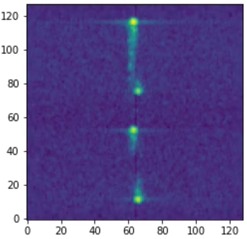
I follow the DCA1000EVM CLI Software User Guide to collect the raw data from the DCA1000 with an AWR 1843BOOST in Windows. Everything is Ok and I collect the raw data successfully, but the data is just incorrect. See the range-doppler map I got as below, only one target is moving but there are 4 targets showing in the range-doppler image. 

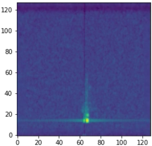
After that, I use the mmwave studio to repeat the experiment and collect the raw data. Then I generate another range-doppler map as below, you can see there is only one target shown as expected.

So there are two differences between these two cases: 

1) DCA1000EVM CLI Software   vs    mmwave studio

2) 18xx_demo.bin from the mmWave_Demo_Visualizer     vs   xwr18xx_radarss.bin & xwr18xx_masterss.bin from mmwave studio

Could someone help me to see what's wrong with this?

Best,

Kevalen

  • Hi Kevalen,

    • Have you configured the front end with the same parameters in both the cases?
    • In your first case, can you elaborate the steps you have taken in detail? (Configuring the DCA capture, LVDSStream config etc.)

    Regards,

    Kaushik

  • Hi Kaushik,

    Thank you for your help!

    1) Yes, I configured the AWR1843 with the same parameters in both cases. The configured parameters are shown in the two pictures I presented above.

    2)  The steps I have taken for the first case are as below:

    I just followed the instructions in the DCA1000EVM CLI Software User Guide to configure the DCA1000 and start the data collection:

    1. Configure FPGA
    Black small square Ensure JSON config file (CLI) and Script config file (RADAR EVM) data format mode are in sync

    Black small square Command - DCA1000EVM_CLI_Control.exe fpga configFile.json

    2. Configure record delay

    Black small square Command - DCA1000EVM_CLI_Control.exe record configFile.json

    3. Start the record

    Black small square Ensure JSON config file (CLI) and Script config file (RADAR EVM) data logging mode are in sync

    Black small square Command - DCA1000EVM_CLI_Control.exe start_record configFile.json

    4. Stop the record after recording data

    Black small square Command - DCA1000EVM_CLI_Control.exe stop_record configFile.json

    The files required for CLI execution are copied from the MMWAVE_STUDIO 02_01_01_00.

    The content of the configFile.json is shown below:

    {
    "DCA1000Config": {
    "dataLoggingMode": "raw",
    "dataTransferMode": "LVDSCapture",
    "dataCaptureMode": "ethernetStream",
    "lvdsMode": 2,
    "dataFormatMode": 3,
    "packetDelay_us": 25,
    "ethernetConfig": {
    "DCA1000IPAddress": "192.168.33.180",
    "DCA1000ConfigPort": 4096,
    "DCA1000DataPort": 4098
    },
    "ethernetConfigUpdate": {
    "systemIPAddress": "192.168.33.30",
    "DCA1000IPAddress": "192.168.33.180",
    "DCA1000MACAddress": "12.34.56.78.90.12",
    "DCA1000ConfigPort": 4096,
    "DCA1000DataPort": 4098
    },
    "captureConfig": {
    "fileBasePath": "./Radar_raw_data/",
    "filePrefix": "adc_data",
    "maxRecFileSize_MB": 1024,
    "sequenceNumberEnable": 1,
    "captureStopMode": "infinite",
    "bytesToCapture": 4000,
    "durationToCapture_ms": 4000,
    "framesToCapture": 40
    },
    "dataFormatConfig": {
    "MSBToggle": 0,
    "laneFmtMap": 0,
    "reorderEnable": 1,
    "dataPortConfig": [
    {
    "portIdx": 0,
    "dataType": "complex"
    },
    {
    "portIdx": 1,
    "dataType": "complex"
    },
    {
    "portIdx": 2,
    "dataType": "complex"
    },
    {
    "portIdx": 3,
    "dataType": "complex"
    },
    {
    "portIdx": 4,
    "dataType": "complex"
    }
    ]
    }
    }
    }


    As for configuring the AWR1843, the configure file is shown below:

    % ***************************************************************
    % Created for SDK ver:03.02
    % Created using Visualizer ver:3.5.0.0
    % Frequency:77
    % Platform:xWR18xx
    % Scene Classifier:best_range
    % Azimuth Resolution(deg):15 + Elevation
    % Range Resolution(m):0.244
    % Maximum unambiguous Range(m):25
    % Maximum Radial Velocity(m/s):12.36
    % Radial velocity resolution(m/s):0.2
    % Frame Duration(msec):33.333
    % RF calibration data:None
    % Range Detection Threshold (dB):15
    % Doppler Detection Threshold (dB):15
    % Range Peak Grouping:enabled
    % Doppler Peak Grouping:enabled
    % Static clutter removal:disabled
    % Angle of Arrival FoV: Full FoV
    % Range FoV: Full FoV
    % Doppler FoV: Full FoV
    % ***************************************************************
    sensorStop
    flushCfg
    dfeDataOutputMode 1
    channelCfg 15 7 0
    adcCfg 2 1
    adcbufCfg -1 0 1 1 1
    profileCfg 0 77 8 7 18.25 0 0 60 1 128 12499 0 0 30
    chirpCfg 0 0 0 0 0 0 0 1
    chirpCfg 1 1 0 0 0 0 0 4
    chirpCfg 2 2 0 0 0 0 0 2
    frameCfg 0 2 128 0 33.333 1 0
    lowPower 0 0
    guiMonitor -1 1 1 0 1 0 0
    cfarCfg -1 0 2 8 4 3 0 15 1
    cfarCfg -1 1 0 8 4 4 1 15 1
    multiObjBeamForming -1 1 0.5
    clutterRemoval -1 0
    calibDcRangeSig -1 0 -5 8 256
    extendedMaxVelocity -1 0
    lvdsStreamCfg -1 0 1 0
    compRangeBiasAndRxChanPhase 0.0 1 0 1 0 1 0 1 0 1 0 1 0 1 0 1 0 1 0 1 0 1 0 1 0
    measureRangeBiasAndRxChanPhase 0 1.5 0.2
    CQRxSatMonitor 0 3 4 31 0
    CQSigImgMonitor 0 63 4
    analogMonitor 0 0
    aoaFovCfg -1 -90 90 -90 90
    cfarFovCfg -1 0 0 24.99
    cfarFovCfg -1 1 -12.36 12.36
    sensorStart
    

    3) I also would like to share the configured parameters that I have used when I used the mmwave studio for collecting raw data.

    DCA.setup.json

    {
      "createdByVersion": "2.1.0",
      "createdOn": "2023-03-22T16:41:23.4877952-07:00",
      "configUsed": "C:\\ti\\mmwave_studio_02_01_01_00\\mmWaveStudio\\JSONSampleFiles\\18xx\\0322.mmwave.json",
      "captureHardware": "DCA1000",
      "DCA1000Config": {
        "dataLoggingMode": "raw",
        "dataTransferMode": "LVDSCapture",
        "dataCaptureMode": "ethernetStream",
        "packetSequenceEnable": 1,
        "packetDelay_us": 25
      },
      "mmWaveDevice": "awr1843",
      "operatingFreq": 77,
      "mmWaveDeviceConfig": {
        "RS232COMPort": "COM3",
        "RS232BaudRate": "115200",
        "radarSSFirmware": "C:\\ti\\mmwave_studio_02_01_01_00\\rf_eval_firmware\\radarss\\xwr18xx_radarss.bin",
        "masterSSFirmware": "C:\\ti\\mmwave_studio_02_01_01_00\\rf_eval_firmware\\masterss\\xwr18xx_masterss.bin"
      },
      "capturedFiles": {
        "numFilesCollected": 1,
        "fileBasePath": "C:\\ti\\mmwave_studio_02_01_01_00\\mmWaveStudio\\PostProc",
        "files": [
          {
            "rawFileName": "adc_data_Raw_0.bin",
            "processedFileName": "adc_data.bin",
            "processedFileSummary": {
              "numZeroFillBytes": 0
            }
          }
        ]
      }
    }

    awr1843.mmwave.json

    {
      "configGenerator": {
        "createdBy": "mmWaveStudio",
        "createdOn": "2023-03-22T16:07:19.4151361-07:00",
        "isConfigIntermediate": 1
      },
      "currentVersion": {
        "jsonCfgVersion": {
          "major": 0,
          "minor": 4,
          "patch": 0
        },
        "DFPVersion": {
          "major": 1,
          "minor": 2,
          "patch": 0
        },
        "SDKVersion": {
          "major": 3,
          "minor": 0,
          "patch": 0
        },
        "mmwavelinkVersion": {
          "major": 1,
          "minor": 2,
          "patch": 0
        }
      },
      "lastBackwardCompatibleVersion": {
        "DFPVersion": {
          "major": 1,
          "minor": 1,
          "patch": 0
        },
        "SDKVersion": {
          "major": 2,
          "minor": 0,
          "patch": 0
        },
        "mmwavelinkVersion": {
          "major": 1,
          "minor": 1,
          "patch": 0
        }
      },
      "regulatoryRestrictions": {
        "frequencyRangeBegin_GHz": 77,
        "frequencyRangeEnd_GHz": 81,
        "maxBandwidthAllowed_MHz": 4000,
        "maxTransmitPowerAllowed_dBm": 12
      },
      "systemConfig": {
        "summary": "This is a comments field not passed to device",
        "sceneParameters": {
          "ambientTemperature_degC": 20,
          "maxDetectableRange_m": 10,
          "rangeResolution_cm": 5,
          "maxVelocity_kmph": 26,
          "velocityResolution_kmph": 2,
          "measurementRate": 10,
          "typicalDetectedObjectRCS": 1
        }
      },
      "mmWaveDevices": [
        {
          "mmWaveDeviceId": 0,
          "rfConfig": {
            "waveformType": "legacyFrameChirp",
            "MIMOScheme": "TDM",
            "rlCalibrationDataFile": "",
            "rlChanCfg_t": {
              "rxChannelEn": "0xF",
              "txChannelEn": "0x7",
              "cascading": 0,
              "cascadingPinoutCfg": "0x0"
            },
            "rlAdcOutCfg_t": {
              "fmt": {
                "b2AdcBits": 2,
                "b8FullScaleReducFctr": 0,
                "b2AdcOutFmt": 1
              }
            },
            "rlLowPowerModeCfg_t": {
              "lpAdcMode": 0
            },
            "rlProfiles": [
              {
                "rlProfileCfg_t": {
                  "profileId": 0,
                  "pfVcoSelect": "0x0",
                  "pfCalLutUpdate": "0x0",
                  "startFreqConst_GHz": 77.0,
                  "idleTimeConst_usec": 8.0,
                  "adcStartTimeConst_usec": 7.0,
                  "rampEndTime_usec": 18.25,
                  "txOutPowerBackoffCode": "0x0",
                  "txPhaseShifter": "0x0",
                  "freqSlopeConst_MHz_usec": 60.012001037597656,
                  "txStartTime_usec": 1.0,
                  "numAdcSamples": 128,
                  "digOutSampleRate": 12499,
                  "hpfCornerFreq1": 0,
                  "hpfCornerFreq2": 0,
                  "rxGain_dB": "0x1E"
                }
              }
            ],
            "rlChirps": [
              {
                "rlChirpCfg_t": {
                  "chirpStartIdx": 0,
                  "chirpEndIdx": 0,
                  "profileId": 0,
                  "startFreqVar_MHz": 0.0,
                  "freqSlopeVar_KHz_usec": 0.0,
                  "idleTimeVar_usec": 0.0,
                  "adcStartTimeVar_usec": 0.0,
                  "txEnable": "0x1"
                }
              },
              {
                "rlChirpCfg_t": {
                  "chirpStartIdx": 1,
                  "chirpEndIdx": 1,
                  "profileId": 0,
                  "startFreqVar_MHz": 0.0,
                  "freqSlopeVar_KHz_usec": 0.0,
                  "idleTimeVar_usec": 0.0,
                  "adcStartTimeVar_usec": 0.0,
                  "txEnable": "0x2"
                }
              },
              {
                "rlChirpCfg_t": {
                  "chirpStartIdx": 2,
                  "chirpEndIdx": 2,
                  "profileId": 0,
                  "startFreqVar_MHz": 0.0,
                  "freqSlopeVar_KHz_usec": 0.0,
                  "idleTimeVar_usec": 0.0,
                  "adcStartTimeVar_usec": 0.0,
                  "txEnable": "0x4"
                }
              }
            ],
            "rlFrameCfg_t": {
              "chirpEndIdx": 2,
              "chirpStartIdx": 0,
              "numLoops": 128,
              "numFrames": 0,
              "framePeriodicity_msec": 33.333,
              "triggerSelect": 1,
              "numDummyChirpsAtEnd": 0,
              "frameTriggerDelay": 0.0
            },
            "rlBpmChirps": [],
            "rlRfPhaseShiftCfgs": [],
            "rlRfProgFiltConfs": [],
            "rlLoopbackBursts": [],
            "rlDynChirpCfgs": [],
            "rlDynPerChirpPhShftCfgs": []
          },
          "rawDataCaptureConfig": {
            "rlDevDataFmtCfg_t": {
              "iqSwapSel": 0,
              "chInterleave": 1
            },
            "rlDevDataPathCfg_t": {
              "intfSel": 1,
              "transferFmtPkt0": "0x1",
              "transferFmtPkt1": "0x0",
              "cqConfig": 2,
              "cq0TransSize": 132,
              "cq1TransSize": 132,
              "cq2TransSize": 72
            },
            "rlDevLaneEnable_t": {
              "laneEn": "0x3"
            },
            "rlDevDataPathClkCfg_t": {
              "laneClkCfg": 1,
              "dataRate_Mbps": 600
            },
            "rlDevLvdsLaneCfg_t": {
              "laneFmtMap": 0,
              "laneParamCfg": "0x1"
            }
          },
          "monitoringConfig": {
          }
        }
      ],
      "processingChainConfig": {
        "detectionChain": {
          "name": "TI_GenericChain",
          "detectionLoss": 1,
          "systemLoss": 1,
          "implementationMargin": 2,
          "detectionSNR": 12,
          "theoreticalRxAntennaGain": 9,
          "theoreticalTxAntennaGain": 9
        }
      }
    }
    

    Feel free to let me know if you want more info about the procedures of my radar raw data collection.

    Thanks and regards,

    Kevalen

  • Hi Kevalen,

    On first look, your configuration method seems to be okay.

    Is it possible for you to perform a 2D FFT of both your data (from Studio / CLI app) on MATLAB and share the results? This is to check whether it is the data itself that has gone for a toss or if it is something else in the setup. Please ensure that your environment is same in both the cases.

    Regards,

    Kaushik

  • Hi Kaushik,

    Thanks for the reply. In fact, I first used python (although not MATLAB) to process these radar raw data, and then found this problem. In order to ensure that it is not a problem with my python code, I switched to mmwave studio to process these radar raw data. The result is still incorrect as I presented in the first post.
    The following are the two range-doppler maps generated by using python to process the radar raw data collected in these two cases:

    RA map for the data from CLI app:

    RA map for the data from Studio:

    As you can see, the problem persists with using python to process the raw data. And I have set the environment the same in both cases.

    Best regards,

    Kevalen

  • Hi Kevalen,

    Thank you for your confirmation. Can you perform the following experiments on your end?

    • Set the number of frames to 1 (instead of infinite mode) in both the cases and match the byte size of data captured. (Will verify a few configs regarding num samples and chirps actually captured)
    • Keep a strong reflector at known distance, perform 1D FFT on data captured by both the tools and verify that the profile and data format is accurate. (Should have peak in known location in both cases).

    Regards,

    Kaushik

  • Hi Kaushik,

    Thanks for the suggestions. I will conduct the experiments accordingly. Currently, I am working on a deadline for next Monday and will try to get back to you with the experiments' results next week. Hope that is not too late.

    Best regards,

    Kevalen

  • Sure. You can get back at your convinience.

    Regards,

    Kaushik