This thread has been locked.

If you have a related question, please click the "Ask a related question" button in the top right corner. The newly created question will be automatically linked to this question.

TMAG5170: Assorted Power and Timing Questions

Part Number: TMAG5170

Question 1. How much power does the TMAG5170 device use when transitioning from one operating mode to another? 

For example,

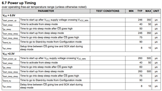
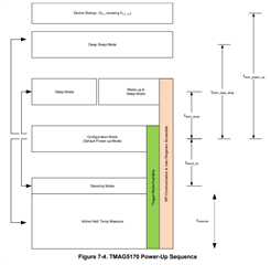
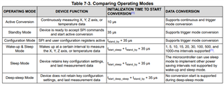
-> transitioning from Configuration mode to Active Conversion mode takes approximately 125uS

-> does the device use Configuration mode levels of power during this 125uS?

-> does the device use Active Conversion mode levels of power during this 125uS?

Question 2: Also, does it take another 125uS for the chip to transition from Active mode to configuration mode? Or how long does it take to transition from Active mode to one of the other modes? 

Question 3: Can the TMAG settings registers be modified in Active and Standby mode, or only in configuration mode? 

Question 4: How long do diagnostics take to run, when enabled? How much time is added to tmeasure?

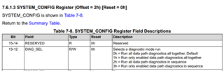
Question 5: What is the meaning of the different diagnostic mode runs? 

-> What does "run data path diagnostics all together" mean? 

-> What does "Run only enabled data path diagnostics all together mean? I thought the enabled diagnostics can simply be enabled / disabled all together, not individually?

-> What does "Run all data path diagnostics in sequence" mean? Significance of all together vs in sequence? Time delay of all together vs in sequence? 

-> What does "Run only enabled data path diagnostics in sequence" mean?  I thought the enabled diagnostics can simply be enabled / disabled all together, not individually?

  • IF the chip select goes low, but no communication occurs - does the TMAG chip register that as an SPI communication error? 

    For instance, could you have the chip select go low for a short duration to cause a conversion. Then have it go high. Then later, have it go low again for an actual communication? 

  • Chris,

    Thanks for reaching out on E2E with your questions.

    1. This isn't within the datasheet, so I don't have a reference on hand.  I will try to go and measure with a current probe or power monitor and get back to you on this by Monday.
    2. Transition times are shown in section 6.7 and figure 7-4:

      Approximate time to initiate a conversion is in table 7-3:

      I don't see a specified number for the transition from Active measure to configuration mode.  I would expect it to be the same or faster.  In configuration mode, the device is not running the high speed oscillator.  I will try to capture this transition when I measure current during the transition.
    3. The device registers can be set during configuration mode and active mode.  In sleep mode, initiating SPI will wake the device.
    4. (and 5) Timing on diagnostics will vary based on settings

      In "sequence" means that one diagnostic test is run per conversion cycle and that the device will step through the enabled diagnostics.  "Run together" means that all enabled diagnostics are run every conversion cycle. Each diagnostic test fills the normal 25 us conversion cycle. Setting to run only enabled diagnostics will run magnetic channel tests for the axes enabled for measurement and the AFE.

      For more details and example timing diagrams I would recommend requesting the Safety Manual from the TMAG5170-Q1 product page:
  • Chad,

    I attempted a test of a single unit on an EVM with power supplied from an external source at 3.3V.  I connected a current probe about my Vcc wire and set a trigger on my CS pin. For this particular device,  I it took about 10 us from CS returning high at the end of the SPI write until current was stabilized when switching from Active mode to Configuration mode.  Running from Configuration mode to Active mode required about 130 us for the current to stabilize at the Active mode nominal value.  

    For triggering a conversion using CS, it is possible to send just a pulse on CS as a trigger without the reset of the SPI communication.  However, I believe this should also result with an SPI clock error since it did not receive 32 clocks.  If you'd like to run this way, it might be helpful to keep CRC enabled to verify data integrity during communications. 

    Thanks,

    Scott

  • Hi Scott, 

       thanks for taking the time to measure that. 

    How much current does the TMAG draw during the transition period? 

  • Or how would I estimate the current draw? For example, would I use a trapezoidal approximation of current draw from Active Mode -> Configuration Mode? 

  • It wasn't a gradual increase which you might estimate using a trapezoidal response.  During the transition, the current remained constant through most of the delay and then quickly steps to the final current, with only a slight rounding off as it reached the final value.  

    Thanks,

    Scott

  • thank you 

  • So for clarity, I can project the current consumption during the transition as being the current used before the transition? 

    so for example, for configuration -> active mode, the current consumed during the transition time is approximately the same as the current consumed during configuration mode normally. 

                              for active -> configuration mode, the current consumed during the transition time is approximately the same as the current normally consumed during active mode. 

  • Yes.  The measured current remained constant for me for the duration of the state change delay, and then steps quickly to the final current.  So switching from config mode to active mode, the current holds at the config mode level.  When changing from active mode to config mode, the current will holds at the active mode level.