This thread has been locked.

If you have a related question, please click the "Ask a related question" button in the top right corner. The newly created question will be automatically linked to this question.

LDC1612: Measurement result changes when power supply voltage of LDC1612 changes from 2.7V to 3.6V ?

Part Number: LDC1612

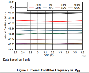
LDC1612 has operating voltage of 2.7V to 3.6V. For a particular set of LC value and environment, will the measurement result change if the operating voltage changes from 3.7V to 3.6V ? Thanks.

  • Hello Nikolaus,

    3.7V is outside of the recommended operating range which is where we guarantee part performance, but it is still within the absolute max range, so your device should not break.  How the device operation will degrade, I am not entirely certain.  However, based on Figure 9 of the datasheet, I suspect the oscillator may deviate from its normal value.  As you can see in figure 9, the oscillator frequency is relatively stable or constant for a given temperature over the operating range.  Outside of this range there might be a drastic change, which would affect your measurement accuracy.

    I will check with my team though, and give you an update if I find any more information on how performance might change.

  • Thanks Patrick.

    I am also interested to know if for a particular LC configuration, for example if L is measured to 100uH at 2.7V VCC, if I raise the VCC to 3.6V, is the measurement of L also having result of 100uH ? Does it related to the VCC supplied ? Thanks.

  • Hello Nikolaus,

    Based on the figure above, the internal oscillator does fluctuate some over VCC.  It looks like +-1kHz.  The oscillator serves as reference for comparing against the sensor oscillator and used for determining L, Rp, and target distance.  Our datasheet does not elaborate too much on how that is determined, but I think our device counts when the oscillators cross a certain threshold and calculates how many reference oscillator crossings per sensor crossing.  Assuming Ref Oscillator typ of 43.35MHz with a fluctuation of +-1kHz and fsensor of 1kHz or 10MHz to divide sensor period by ref period for a value that we will just call Crossings, we can then take the ratio of (Crossings_-1KHz - Crsossing_typ)/Crossings_Typ, to get -4.6135E-5.  This is the deviation in crossings I would expect based on the above figure.  As this relates to time, which relates to frequency, and frequency has the relation to L as f = 1/(2pi*sqrt(LC)). I would square this value then multiply it by your inductor value to estimate how much the inductor value might fluctuate based on VCC changing. That value is less than a 1pH.