This thread has been locked.

If you have a related question, please click the "Ask a related question" button in the top right corner. The newly created question will be automatically linked to this question.

TMAG5170: Integrating off axis encoder with BLDC

Part Number: TMAG5170
Other Parts Discussed in Thread: TMAG5115, TMAG5110, TMAG5111, DRV5055, TMAG5253, TMAG5273

Hello,

I am using the DRV8350FHRTVR motor drive and F280041CRSHS micro in a custom board design.  We are currently using InstaSPIN-FOC to control a sensorless BLDC PM motor.

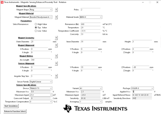
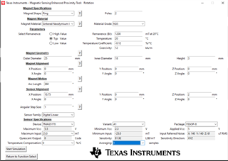
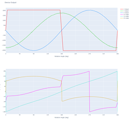
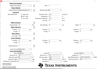
I would like to add position feedback to the system.  An off axis sensor will my system the easiest.  My motor shaft passes through my board so a TMAG5170 might do the trick.  

Will this type of sensor work for a position feedback for a BLDC so I don’t have the typical sensorless startup issues?  How do I determine if the sensor/target magnet are in too close of proximity to the stator/rotor magnets or is that not a problem?

Thank you 

  • Michael,

    Thank you for reaching out on E2E with your question.  TMAG5170 can be used in an off-axis alignment to measure the position of the motor.  It is likely that the field components measured from your spinning magnet with have unequal amplitude, so you will need to do some amplitude correction to help linearize your angle result.

    I would recommend trying to achieve as high of a SNR as possible on your measurement.  This can be done by reducing air gap between the sensor and magnet, using a strong magnetic material, and by enabling averaging within the device.  Averaging will effectively reduce the observed noise, but does add sample delay of which you should be aware.  At high speeds this delay will influence timing of your system control. 

    Thanks,

    Scott

  • Scott,

    Thank you for the quick response.  Does enabling amplitude linearization happen with in the TMAG5170 or does that have to be done separately?  How large of a sample delay does it add?  What is considered high speed?

    Are there a different solution you might recommend?  Is it possible for me to email you a screen shot of my layout to help get any feedback you might have?

    Regards

  • Michael,

    The amplitude correction is done using the GAIN_SELECTION and GAIN_VALUE register settings.  One axis may be selected to adjust gain by a scalar value ranging from 0 to 2.  If your manufacturing process is repeatable, you may be able to characterize the best typical value for your system, but optimal performance would require measuring each system as part of an end of line calibration. There is no delay associated with this correction to the final measurement.

    The update rate is shown in this table

    It is difficult for me to quantify what is too fast, however, since this largely depends on how much phase delay you can accept for your needs and the level of averaging selected.  The fastest sampling option would be to set the device to capture 2 axes of data with averaging set to 1x (13.3 ksps).  You should start here and consider how much the magnet will rotate at the speeds you are considering over the course of one sample phase.  

    Thanks,

    Scott

  • Does a TMAG5170 system tend to be equal or better than a TMAG5115 architecture?  I imagine if the 5170 is superior to 5115 then the 5170 could be appropriate.
    Are there any real world examples/articles that can be shared on applying TMAG5170?

    My design does not require high positional control. The motor turns only in one direction but needs to be able to start under load, without reversals, which is the typical sensorless challenge.  The motor starts/stops and has variable speed settings.  

    My max rpm is up to ~2400rpm. 

    Does that help to understand my needs?  The website for my product is here  
    https://kobofishing.com/

  • Michael,

    TMAG5170 will produce an output which can be used to track the X,Y, and Z components of the magnetic flux density vector.  The output varies linearly as the field changes.  Using a configuration that produces sine/cosine inputs allows the device to calculate the absolute angle created by any two field vectors.

    By comparison the TMAG5115 is a latch type device.  It can be used to track rotation of a magnet and will toggle the output between high and low states as opposing magnetic poles are presented to the sensor.  Using a standard dipole magnet, you would only be able to detect when transitions happen with 180 degrees separation.  As the pole count increases, you would have more resolution.  This might be helpful in tracking speed or detecting an exact stopping point. If you happen to be at the midpoint between switching locations, you would have trouble detecting which direction the shaft turns until the next transition point occurs.

    We have an application note here where we calibrated actual angle measurements for TMAG5170 in a low speed setting:

    https://www.ti.com/lit/an/sbaa463a/sbaa463a.pdf

    and here is a document which describes various calibration methods:

    https://www.ti.com/lit/an/sbaa539a/sbaa539a.pdf

    I think 2400 RPM should be within a reasonable speed for TMAG5170. In this case each revolution requires about 0.025 seconds.  At 32x averaging it should be possible to configure the device for about 600 ksps, or about 0.00166 seconds per sample.  You would be able to capture about 15 measurements per revolution at this rate.  Since you do not require high precision control, you could probably set averaging at the default 1x and then have new data available every 75 us.  

    Thanks,

    Scott

  • What ends up happening at say 5000rpm?  With no averaging I see a plot that shows ~2 degrees of phase error, with 32x averaging I see about 50 degrees of phase error.   Fig 5-4. TMAG5170 Angle Phase error vs Rotation speed (can't find the doc but I have a screen shot).

    When monitoring the rotor angle it can be off by 50 degrees?  Or is lagging the correct term?  Does this then mean I need to compensate for the 50 degrees to know where my rotor position is so I have some amount of torque performance at that speed?

    Is there an off axis solution that can perform at higher speeds, say 3-5k RPM?  My current motor will not run higher than the 2.4k RPM, I'm just thinking of future applications and potential of being limited by this sensor. 

  • Michael,

    The plot you are referring to is in the second application note referenced above.  What this plot is trying to show is how much the magnet will rotate over the sample conversion period of the sensor.  So at 5000 rpm, the magnet turns at 30,000 degrees per second.  For 1x the conversion time is 75 us, so the magnet will rotate about 2.25 degrees during this time.  At 32x the conversion takes about 1.625 ms and the magnet will rotate 48.75 degrees.

    You are correct that this indicates the lag of the measurement to the rotor position, and this is common for any system.  The best practice is to always evaluate this delay, and then apply a forward calculation based on the rotor speed to determine the actual position.

    All of our 3D sensor have a similar sample rate, so you would be faced with the same limitation.  We do have a 2D AMR based sensor which is faster, but this device (TMAG6180) is meant for on-axis applications.  If you can place the sensor accurately, there should be a location where you can orient the sensor to capture two field components with equal magnitude.

    Thanks,

    Scott

  • Understood.

    So if I'm not position critical at high RPM then a forward calculation based on rotor speed could be a fair option if I start to reach limitations of the sensor.  Would you agree with that?

    Is the below in reference to using a single TMAG5170?  My motor shaft is normal and passes through my board. 

    If you can place the sensor accurately, there should be a location where you can orient the sensor to capture two field components with equal magnitude.

    Thanks,

    My design options I was considering:
    1. The sensor would either sit between the diametric magnet face and the PCB.  
    2. The sensor would sit just outside the OD of the magnet and ideally within the width of the sensor

    Do those descriptions make sense?

  • Yes, if you are running high RPM, you will need to forward calculate and this should be a workable solution.

    With TMAG5170 you have more flexibility on your angle measurement because we are able to capture all three field components.  An example of what I was referring to is shown here:

    This simulation was done using this tool:

    https://www.ti.com/tool/download/MAGNETIC-SENSE-ENHANCED-PROXIMITY/

    and these settings:

    In this case the Y and Z components are well matched at this spacing from the magnet.  The sensor is almost co-planar to the magnet bottom, but not exactly.  Using TMAG6180 in this position would require rotating the sensor to detect the Y and Z components. Placing TMAG5170 here would minimize the effort on correcting gain, and you would just configure the device to report angle using these axes.

    Thanks,

    Scott

  • I will review the simulation tool.

    My magnet would be a ring - approximately 15mm ID x 25-32mm OD.  Is there a "ring magnet" option?

    Is there anything I can do to consider the proximity to the motor being an issue?  I have implemented a handful of on axis diametric halls for slower encoders applications and linear halls for displacement detection.  Proximity to motors has always been a concern but I have yet to have it be a problem.

  • Michael,

    The tool does not account for stray fields.  Ring magnets a certainly possible though, and you are able to increase the pole count if desired.

    I created another setup more closely matched to your magnet requirements.  In this case you might use the +/- 25 mT range on the A1 variant:

    Thanks,

    Scott

  • I will look into the data more closely.

    I have been able to source some different multi pole and diametric targets that fit my system. 
    Can I use the TMAG5170 with multipole or am I better of the diametric?

    Using a pair of TMAG5110 or TMAG5111, would either of these only work with a diametric magnet or only the multipole?

    I guess a different option would be to use a pair of DRV5055s with a multipole magnet?

    Do the same high speed considerations become a factor for the paired sensor approach?

  • TMAG5170 can sense the field from either diametric or multi-pole magnets.  When using a multi-pole magnet, you lose the ability resolve the absolute angle of the mechanism.  That is, you now have n points which can map to your measured angle value, where n is the number of pole pairs.  Multi-pole ring magnets do tend to be more expensive, but you should be able to work with one if desired.

    TMAG5110 or TMAG5111 are able to detect two components of the magnetic field, and you should wind up being able to produce quadrature data.  For a standard diametric magnet, there are 4 output states per revolution, and thus you can determine which quadrant you are in.  If you use a multi-pole ring magnet, then you will get 4 states per pair, so your resolution improves.  The multi-pole ring magnet tends to have a weaker field, so you do need to make sure you have enough input to always trigger BOP  and BRP.

    DRV5055 can also work here, but two sensors placed 90 degrees apart are needed to measure angle.

    You will have some high speed considerations with DRV5055 when you add in the time for your ADC to convert the output.  Essentially you will also experience lag from that conversion process and need to allow time for it.  

    Thanks,

    Scott

  • With the multipole magnet you won't have absolute angle of the mechanism itself, but I will have the ability to know the electrical angle.  Is that correct?

    Below is the setup I can place my sensor and magnet I have been able to source so far. 

    For the device output, I shouldn't care that the X Output is saturating?  
    I also only care about the YZ Angle for tracking the absolute position?
    As long as the Y and Z outputs (in this position) are not clipping or saturating (like X output) I will get a good reading?
    What is the function of "Maximum input" on sensor specifications?

    I figure I want to maximize the output reading while keeping the target/sensor relationship as close as possible.  This will help avoid noise from the proximity I have to the rotor/stator, if it is a problem.  Is that the right thought process?

  • Michael,

    You are correct here.  If you do not use the X input, it is not important whether or not the input saturates.  In the real device, you do have the ability to set the axes sensing range independently, but we have coded the tool to expect them to match.

    Additionally, we have no way of knowing in advance which two axes you plan to use, so we plot angle results for all three combinations.  You can ignore the two which use the saturated X output.  If helpful, you can click the legend entries and hide the lines you are not interested in.

    The minimum input should match the maximum input.  The maximum input allows you to adjust the sensitivity range (i.e. +/- 25 mT, +/- 50 mT, or +/- 100 mT)

    I think your approach is good.  We would typically want to have the SNR as large as possible to reduce effects of noise on your angle calculation.  Then, the next step is to increase averaging if you are able to manage the extra latency.

    You probably notice there is slight non-linearity to your angle result, which is caused by the amplitude mismatch between Y and Z.  With the actual device you could adjust the sensitivity gain of either Y or Z and this will produce the best result..

    Thanks,

    Scott

  • With the multipole magnet you won't have absolute angle of the mechanism itself, but I will have the ability to know the electrical angle (assuming the target and rotor have the same pole pair).  Is that correct?

    Based on our conversation so far, is there potentially a better solution you can think of in terms of performance?  Without having an on axis sensor.  TMAG5273, TMAG5253 or is the 5170 the best I can expect?

  • Michael,

    You are right again.  For multi-pole you end up adding ambiguity of which pole pair you are observing, so you lose absolute angle of the mechanism.  However, for each pole pair you can observe 360 degree of angle change for each pole pair.  This may improve angular resolution somewhat, but you wind up also sacrificing the peak input amplitude you observe.  Placing the sensor closer to a multipole magnet tends to result with some distortion from an ideal sine and cosine input, so you will have more angle non-linearity as a result. You may be able to improve resolution somewhat, but these magnets are often more expensive.

    Here are the main options when considering a diametric magnet:

    • On-Axis w/ TMAG5170 (SPI) or TMAG5173 (I2C) provides absolute position over full 360 degree rotation using a diametric magnet.  Conversion time and communication add to latency of measurement. On axis is the least compact arrangement.  TMAG5273 can be used as well, as a lower cost / lower performance device.
    • Off-Axis  w/ same sensors.  This will be more compact in solution size, but you will need to do more correction for amplitude and mechanical errors.
    • On-Axis w/ TMAG6180 or TMAG6181.  These AMR based sensors are analog output with differential sine and cosine.  Automatic gain control will adjust itself to maintain a fixed output magnitude, so this device is best positioned on-axis.  This device is high bandwidth so your measurement will mostly be limited by your ADC performing the conversion.
    • DRV5055 or TMAG5253 offer ratiometric sensitivity which adjusts itself for changes in Vcc.  This is meant to keep ADC conversion results constant as battery voltage droops.  For full angle measurements it will require two of these devices installed 90 degrees separated from each other about the magnet.  With analog output, your system latency will also be mostly determined by your ADC sampling.
    • TMAG5110 or TMAG5111 these can be placed in most positions around a diametric magnet (90 degree resolution) or off-axis with a multi-pole ring (no field at the center).  These will have a fast response and do not require ADC sampling, but you have limited resolution with 4 positions per pole pair and only relative angle accuracy.  That is, you can only track angle changes based on your start point at power up.

    Since in your case we need to exclude the on-axis alignment, I would probably still opt for TMAG5170 or TMAG5173 for the highest accuracy.  There should be locations where you can match two components in amplitude naturally, and this will help minimize the amount of calibration needed.  By maximizing input amplitude and setting averaging at the lowest setting you can sample at the highest rate to reduce latency.

    Thanks,

    Scott

  • TMAG 5170 vs 5173 - the differences here are SPI and I2C?

    5170 comes in two variants 25/50/150 and 75/150/300.  I have sourced the existing magnet in this design.  I also think any other neo diametric I MIGHT need to customize will only get stronger.  Some suppliers complain this spec is fragile.

    With the below hardware (A1) configuration I am saturating 25 and very close to saturating at 50.

    I can move the magnet further away but I figure I would prefer using the A2 variant.  This will allow me to no waste any input range.  This is the correct thought process?  Are there pros/cons to A1 vs A2 input range that I'm missing? 

    I would think having the strong magnet would + higher input range would allow for reduced noise sensitivity - is that true?

    Outside of the previous example shown with 600RPM motor, do you have any knowledge/feedback from applications pushing higher RPMS or times when users had the sensor too close to a motor?

  • The sensitivity ranges do vary on TMAG5173 vs TMAG5170.  You can choose from +/-40 or +/-80 mT.  

    The A1 and A2 variants do have somewhat different tolerances.  I would recommend you compare the spec table for both.  They are too large to comfortable copy and paste here.

    I would also try for a stronger magnet and higher sensing range to improve SNR.

    We have had customers use the device with motorize applications, but I don't know that I have any specific anecdotal RPM values from their final product, and I haven't worked with anybody that reported problems based on the field from the motor altering their measurements.

    Thanks,

    Scott

  • Just to confirm -
    A higher sensing range would be the A2 variant?


    I originally was placing the sensor between the ID/OD of the ring magnet (like below).  What I found is that as I moved the the target closer/further there was a much bigger impact/sensitivity to position. I think it the fields are just weird


    It seems like the more robust approach is to put the sensor on a position outside of the OD of the ring magnet, like below.  I originally was thinking use the A2 version but never get in a position to set the Max Input ABOVE 75.  Setting it at 150 or 300 just ends up minimizing the output signal, 500 or lower.

    If I use the A1 version I can really use 50 or 100.  I feel like I have a better chance of keeping the output signal in the 750/1000 range at worse case.  Having a lower output value is not ideal, I want it as large as possible without saturating.  Is that corret?

    What are your thoughts?

  • Michael,

    The field behavior can be a bit odd for the diametric ring depending on the geometry when the sensor is placed close to the magnet.  It is not uncommon to see some distortion to the magnetic field.  I do agree that it's probably best to place on the OD and to give yourself a bit of range to the magnet to allow for the field to appear more circular.

    The A2 variant does have higher input ranges (+/- 75, +/- 150, and +/- 300 mT).  

    In general, as large as possible applies so long as the input does not become distorted.  Once there is distortion on the input (say from putting the sensor too close to a ring magnet) then you will have an increase in angle non-linearity as well.

    Thanks,

    Scott

  • Sorry to ask similar questions, just want to make sure I understand.

    By distortion do you mean a non circular field?  Or do you mean there being saturation of the sensor?

    If I use the A1 variant I can more easily saturate the sensor because the low range.  Because of that I am able to have a higher output signal. Should I be optimizing position/variant to simply the highest output signal I can get?  When I use the A2 variant I can't saturate the signal so inevitably it seems like the output signal can only be lower.  The larger the output signal is then that increase my ability to overcome noise?

    For example:
    A1 variant has a max input of +/-25.0 with a signal output of +/-1500
    A2 variant has a max input of +/-75.0 with a signal output of +/-1100
    The A1 variant above would be the better choice to overcome noise?

    A1 variant has a max input of +/-25.0 with a signal output of +/-1100
    A2 variant has a max input of +/-75.0 with a signal output of +/-1100
    The A1 variant and the A2 variant have the same ability to overcome noise?

    Is there anything else I am missing? 

  • Michael,

    I mean a non circular field, but saturating the input of the sensor will also produce a kind of distortion, and this would also have a negative impact on linearity of the measurement.

    Comparing the +/-25 mT range to the +/-75 mT range, you should see a 3x reduction in the output code when comparing from A1 to A2 if all other variables are the same.  

    Input referred RMS noise for XY axes at room temp using that A1 variant and no averaging is shown here

    And the same for the A2 variant

    While the max RMS value does increase when going from A1 to A2, if you are able to increase the signal by a more significant amount you should have a measurement which less susceptible to error from noise, but non-circular input or input saturation will not be as easily managed.  Noise can be reduced through over-sampling (averaging), and then accounting for the additional delay.  Angle non-linearity will require calibrated corrections in the MCU to resolve the angle error.

    Thanks,

    Scott

  • Yes, if the other variables were the same then the output signal is 3x reduced for A2.  The point of the examples I listed were to determine if I should just be choosing a configuration with the largest signal output.  

    if you are able to increase the signal by a more significant amount you should have a measurement which less susceptible to error from noise

    Increasing the signal meaning having a larger signal output?

    While the max RMS value does increase when going from A1 to A2

    So the A2 variant is less susceptible to noise by having a higher RMS range?

  • Hello Michael,

    Scott is currently out of office presenting at a trade show so his responses may be delayed a bit. We appreciate your patience!

    Best,

    Isaac

  • For either sensitivity option you should try to use as much of the FS range without saturating the input.  A2 has slightly higher RMS noise than A1, but you can provide a larger total input signal for A2 in order to reach a better SNR.  

    Thanks,

    Scott