This thread has been locked.

If you have a related question, please click the "Ask a related question" button in the top right corner. The newly created question will be automatically linked to this question.

AWR1843BOOST: Error connecting to the target: (Error -6305)

Part Number: AWR1843BOOST
Other Parts Discussed in Thread: AWR1843, UNIFLASH

Tool/software:

Hello,

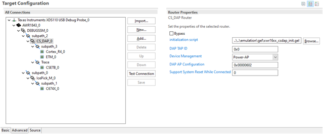
I've encountered a following error message in ccs while connecting a target in Target Configuration using AWR1843BOOST.

First error message is:

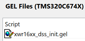
FYI, in the GEL file window it shows:

Then the second error message shows:

When Test Connection is done, it looks successful.

I've tried to clean my workspace by deleting the .metadata folder but it did not help.

Someone suggested it has something to do with 5V power rail instability but the board seems to work fine when I use mmWave Studio for measuring range and angle.

I know there are a couple of threads in the forum asking the same question but I'd like to ask again regarding AWR1843 in particular.

I'm relatively new to TI ccs and boards so detailed instruction would be greatly appreciated.

Thank you

  • Hello,

    Thanks for reaching out regarding your issues getting started with the AWR1843BOOST. A couple of things to get you started on debugging this issue:

    1. Did you specify the AWR1843 device in the target configuration?
      This error appears to be caused by an issue with connecting to the DSP core.
    2. Did you flash the empty image on the device before attempting to connect?
      This shouldn't be needed until after you connect and load a program as this empty is primarily used to reset the front-end and DSS, but it will help us narrow down potential issues here.
    3. Have you taken a look through the following software guide for Using CCS Debug?
      Most of my previous questions are covered in this document, though this outlines the overall debug flow you should follow

    Let me know if you have any other questions, but please take a look through that software guide.

    Regards,

    Kristien

  • Hi Kristien,

    Thanks for your replay. Before jumping into the answers, just want to tell you I've tried the Functional Mode of this board and it worked just fine showing live data capture. 

     Here are my answers to your questions:

    Did you specify the AWR1843 device in the target configuration?

    Yes. I selected the AWR1843 as shown below. As instructed, I tried to connect Target for C674x first where I got the error message. In one time, C674x was able to be connected but not the Cortex_R4. In other times, even C674x was not connected.

    Did you flash the empty image on the device before attempting to connect?

    I generated an empty bin file and tried to load image using UniFlash but showing the following message. 

    Generating an bin file using Matlab's fread of the pre-built xwr18xx_mrr_demo.bin and fwrite with all zeros filled did not work either, showing the header is not valid.

    Have you taken a look through the following software guide for Using CCS Debug?

    Yes. I've gone through the contents but couldn't find anything helpful. 

    Sorry to give you all bad news but please guide me for the next steps I can try.

    Thanks for your help.

    Reem

  • Hey Reem,

    Thanks for looking into my suggestions. Just one clarification, the empty image I was referencing is the xwr18xx_ccsdebug.bin mentioned in the CCS debug guide. "Empty" images are used for low-power devices and are not completely empty. They are debug images, similar to the ccsdebug images, that still contain image formatting that is needed for the device to recognize the image as acceptable. I apologize for using the wrong reference, so please try to flash the xwr18xx_ccsdebug.bin found under <MMWAVE_SDK3_INSTALL_DIR>\packages\ti\utils\ccsdebug. 

    I also wanted to ask if you attempted to add an image with your first comment. If so, I cannot view whatever it is that was added there.

    Regards,

    Kristien

  • Dear Kristien,

    Sorry for late response and from now on I'll make sure to give you updates in a timely fashion.

    1. Regarding the empty image (xwr18xx_ccsdebug.bin), I did try it and unfortunately it did not work. In fact "Building from source code" guidelines in Resource Explorer/.. examples/..ADAS/.. medium range radar instructed me to do at the first place.

    Here is the link where step-by-step instructions are given that I used:

    https://dev.ti.com/tirex/explore/node?node=A__AKYeTfuZO.zUHnjn7sP9kw__radar_toolbox__1AslXXD__LATEST

    I tried all the way through and I'm stuck at "Building from Source Code and Running" - 5. Running the lab.

    Still the issue of the error connecting to the target (error -6305) exists.

    2. Recently we got a new 1843Boost board since we thought the 5V DC line may be damaged. We followed the instructions given in that link and now the error -6305 did not appear but it said "suspended" when connected to Target:

    In Console, it read:

    "(Error -1065 @0x3C) Unable to access device memory. Verify that the memory address is in valid memory. Mrr_18xx-mss.xer4f: Load failed."

    If possible, we'd like to resolve the issues in each board.

    Please let me know what I can do next.

    Thanks for your help.

    Reem

  • Hey Reem,

    I will need to pass this thread off to another engineer, but I have some last comments and suggestions as shown below.

    Regarding the -6305 error, could you open up your Target Configuration, click on the Advanced tab, and ensure that the CS_DAP_0 initialization script references xwr16xx_csdap_init.gel? This can be found under the following directory <CCS_VER_INSTALL_DIR>/ccs/ccs_base/emulation/gel. The image below shows how that might be referenced relative to the Target Configuration location.

    For the -1065 error, just to double check, you are loading the .xer4f file to the Cortex-R4F and not the C674x, correct? This error can occur if their is a mismatch in memory formatting and the .xer4f file.

    Regards,

    Kristien

  • Hi Kristien,

    Thanks for your reply.

    Luckily both errors were resolved and our two boards showed live data stream correctly in MRRvisualizer. It had something to do with the SOP switch setting. Maybe you could help me get this right. From the 1843boost user's guide as shown below, I thought I should use debug mode, not the functional mode. But only when the SOP is set for functional mode, it works fine. What are the usages of each mode, specially, debug mode?

    Also I'm just wondering at what step I need to resume when the board is powered off and switched back on again? I guess I do not need to flash the empty image (ti\utils\ccsdebug\xwr18xx_ccsdebug.bin) again. Should I start from "Launch target Configuration" or simply "Connect Target"? 

    One last question is that if there is a safer way to power off the board instead of just pulling the plug?

    Thanks for your help again.

    Reem

  • debug mode is used with DCA1000. 

    You do not need to flash the board again. You can change mode to functional and launch target configuration

    Please look through the guide for reset switch