This thread has been locked.

If you have a related question, please click the "Ask a related question" button in the top right corner. The newly created question will be automatically linked to this question.

IWRL6844EVM: xWRL 6844 EVM Calibration

Part Number: IWRL6844EVM
Other Parts Discussed in Thread: AWR6843, AWRL6844

Tool/software:

Hi,

We recently applied for xWRL 6844 EVM from TI and obtained it on February 19th. We are now trying to run it.

During the calibration process, I found that there was no documentation to explain it.


However, when referring to the calibration process of AWR6843, there is no relevant setting for 6844 in mmWave_Demo_Visualizer 3.6.0.

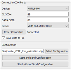
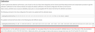
Although it works fine when using the default visualizer (6.0.3.0), a calibration setting is added in the cfg file: measureRangeBiasAndRxChanPhase 1 1.0 0.2

But after running it, no calibration values ​​are returned.


I refer to the visualizer tool file path as follows:

MMWAVE_L_SDK_06_00_03_00\tools\visualizer


The reference manual files are as follows:

radar_toolbox_2_30_00_12/source/ti/examples/Automotive_InCabin_Security_and_Safety/AWRL6844_InCabin_Demos/docs/Seat_Belt_Reminder/AWRL6844_SBR_users_guide.html

Can you tell me the calibration procedure for the complete xWRL 6844 EVM?
Or are we missing some tools?


Thanks

ED

  • Hello,

    Thanks for reaching out over E2E with your question. The calibration data can be acquired by using the Radar Toolbox Applications Visualizer located under <RADAR_TOOLBOX_INSTALL_DIR>\tools\visualizers\Applications_Visualizer, though a slight modification will need to be made. Under the common folder, open up parseTLVs.py, locate the parseRXChanCompTLV function and change compStruct = ‘13f’ to compStruct = ‘33f’. Note: This change only works for xWRL6844 and will break calibration data parsing for any xWRLx432 devices.

    def parseRXChanCompTLV(tlvData, tlvLength, outputDict):
        compStruct = '33f' # for 4x4 devices only
        compSize = struct.calcsize(compStruct)
        coefficients = np.empty(compSize)
        try:
            coefficients = struct.unpack(compStruct, tlvData[:compSize])
        except:
            log.error('RX Channel Comp TLV Parsing Failed')
    
        outputDict['RXChanCompInfo'] = coefficients

    Afterwards, you will have run the Body and Chassis Visualizer from source using Python – i.e., navigate to the Body_And_Chassis_Visualizer folder and run python gui_main.py. Finally, follow the steps below to run the mmWave Demo to acquire coefficients. 

    1. Load the mmwave_demo.appimage found at <MMWAVE_LSDK6_INSTALL_DIR>\examples\mmw_demo\mmwave_demo\prebuilt_binaries\xwrL684x-evm
    2. Set a strong target like corner reflector at the distance of X meter (X less than 50 cm is not recommended) at boresight in a clutter-free environment. A large room or outdoors should be sufficient.
    3. Add the following line to the configuration file intended for use. It is important to calibrate with a configuration file whose frequency range is similar to the range used in operation.
      measureRangeBiasAndRxChanPhase 1 X D
      The first argument "1" is to enable the measurement. The second argument, D, (in meters) is the distance of window around X where the peak will be searched. The purpose of the search window is to allow the test environment from not being overly constrained say because it may not be possible to clear it of all reflectors that may be stronger than the one used for calibration. The window size is recommended to be at least the distance equivalent of a few range bins.
      You can also use the attached .cfg file, but make sure this matches the frequency range you would like to use in operation.
    4. If you do modify your .cfg file, ensure that the configuration file fulfills the following constraints:
      1. Clutter removal is disabled if available – i.e., clutterRemoval 0
      2. TDM MIMO mode is enabled – i.e., chirpComnCfg x x x x 1 x x
      3. Number of Tx and Rx antennas must be 4 and 4 – i.e., channelCfg 153 255 0
    5. Launch the Radar Toolbox Body and Chassis Visualizer from source using Python: python gui_main.py
    6. Select the xWRL6844 as the Device, check Device Manager for your Application port (CLI COM) and Auxillary port (DATA COM), connect to the device, ensure Save Data to File is enabled, select your configuration, and hit Start and Send Configuration
    7. After 100 frames, a binData folder will appear under the Body_And_Chassis_Visualizer folder containing TLV data every 100 frames in the form of a .json file. You can then search for RXChanCompInfo which will contain the coefficients.

    Hopefully this helps, but let us know if you have any other questions.

    Cheers,

    Kristien

    profile_4T4R_tdm_calibration.cfg