


Tool/software:
Hello, I am working in implementing the OPT3004 Ambient Light Sensor to the firmware of an ESP32-S3.
I was able to establish I2C connection reading the values of all registers just fine. However, when trying to change the configuration register it doesn't take effect.
Here is a picture of the logic analyzer when writing and then reading the configuration register:
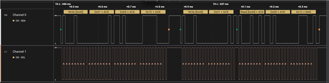
The image doesn't have the best resolution for some reason, here is the data of the image:
Write 0x44 0x01 0xD0 0x7C
Then, the read procedure is: Write 0x44 0x01 Read 0x44 0xD0 0x1C,
Here is the code of my implementation when configuring:
static const uint8_t OPT3004_I2C_ADDR = 0x44; // I2C Address OPT3004
i2c_master_dev_handle_t opt3004_i2c_dev_handle;

typedef enum
{
  OPT3004_REG_RESULT = 0x00,
  OPT3004_REG_CONFIG = 0x01,
  OPT3004_REG_LO_THRESH = 0x02,
  OPT3004_REG_HI_THRESH = 0x03,
  OPT3004_REG_MANUFACTURER_ID = 0x7E,
  OPT3004_REG_DEVICE_ID = 0x7F
} opt3004_reg_addr_t;

typedef union{
  uint16_t reg;
  struct{
    uint16_t exponent:4;
    uint16_t fraction:12;
  } bytes;
} opt3004_reg_t;

typedef union{
  uint16_t conf;
  struct{
    uint16_t range_num_field:4; // R/W full scale range selection
    uint16_t conversion_time:1; // R/W time for conversion 0:100ms 1:800ms
    uint16_t conversion_mode:2; // R/W mode of conversion 00:shutdown 01:singleshot 10-11:continuous
    uint16_t overflow:1; // R 0:light between selected scale 1:light exceeds selected scale
    uint16_t conversion_ready:1; // R 0:conversion not ready 1:conversion ready
    uint16_t flag_high:1; // R 0:light below high threshold 1:light above high threshold
    uint16_t flag_low:1; // R 0:light above low threshold 1:light below low threshold
    uint16_t latch_field:1; // R/W 0:interrupt with no user-controlled clear 1:interrupt with user-controlled clear
    uint16_t polarity:1; // R/W 0:active low 1:active high
    uint16_t mask_exponent:1; // R/W 0:no change to exponent value of register 1:changes the value of exponent to 0000b when range is manually selected
    uint16_t fault_count:2; // R/W number of faults to trigger interrupt 00:1 fault 01:2 faults 10:4 faults 11:8 faults
  } bits;
} opt3004_conf_t;

opt3004_status_t opt3004_init(opt3004_t *opt3004_params)
{
  ESP_LOGI(TAG, "%s - Initializing OPT3004", __func__);
  if (opt3004_params == NULL)
  {
    ESP_LOGE(TAG, "%s - NULL Params", __func__);
    return OPT3004_ERR;
  }
  OPT3004_PARAMS = opt3004_params;
  //Init I2C
  if (opt3004_i2c_init_device() != OPT3004_OK)
  {
    ESP_LOGE(TAG, "%s - Error init I2C", __func__);
    return OPT3004_ERR;
  }
  //Read Manufacturer ID
  uint16_t manufacturerID = 0;
  if (opt3004_read_reg_i2c(OPT3004_REG_MANUFACTURER_ID, &manufacturerID, 0) != OPT3004_OK)
  {
    ESP_LOGE(TAG, "%s - Error reading Manufacturer ID", __func__);
    return OPT3004_ERR;
  }
  ESP_LOGI(TAG, "%s - Manufacturer ID: %04X", __func__, manufacturerID);
  //Read Device ID
  uint16_t deviceID = 0;
  if (opt3004_read_reg_i2c(OPT3004_REG_DEVICE_ID, &deviceID, 0) != OPT3004_OK)
  {
    ESP_LOGE(TAG, "%s - Error reading Device ID", __func__);
    return OPT3004_ERR;
  }
  ESP_LOGI(TAG, "%s - Device ID: %04X", __func__, deviceID);
  //Read Config
  uint16_t conf_reg = 0;
  if (opt3004_read_reg_i2c(OPT3004_REG_CONFIG, &conf_reg, 0) != OPT3004_OK)
  {
    ESP_LOGE(TAG, "%s - Error reading Config", __func__);
    return OPT3004_ERR;
  }
  ESP_LOGI(TAG, "%s - Config register %04X", __func__, conf_reg);
  opt3004_conf_t conf;
  conf.conf = conf_reg;
  ESP_LOGI(TAG, "%s - Configuration", __func__);
  ESP_LOGI(TAG, "%s - Range: %s", __func__, conf.bits.range_num_field == 0b1100 ? "Automatic" : "Manual");
  ESP_LOGI(TAG, "%s - Convertion time: %s", __func__, conf.bits.conversion_time == 0b1 ? "800ms" : "100ms");
  ESP_LOGI(TAG, "%s - Conversion mode: %s", __func__, conf.bits.conversion_mode == 0b00 ? "Shutdown" : conf.bits.conversion_mode == 0b01 ? "One shot" : "Continuos conversion");
  ESP_LOGI(TAG, "%s - Latch: %s", __func__, conf.bits.latch_field == 0b0 ? "Transparent Hysteresis" : "Window Hysteresis");
  ESP_LOGI(TAG, "%s - Polarity: %s", __func__, conf.bits.polarity == 0b0 ? "Active Low Interrupt" : "Active High Interrupt");
  ESP_LOGI(TAG, "%s - Exponent: %s", __func__, conf.bits.mask_exponent == 0b0 ? "No change to exponent value of register" : "Change to exponent value of register");
  ESP_LOGI(TAG, "%s - Fault count: %s", __func__, conf.bits.fault_count == 0b00 ? "1 fault" : conf.bits.fault_count == 0b01 ? "2 faults" : conf.bits.fault_count == 0b10 ? "4 faults" : "8 faults");
  ESP_LOGI(TAG, "%s - Flag high: %d", __func__, conf.bits.flag_high);
  ESP_LOGI(TAG, "%s - Flag low: %d", __func__, conf.bits.flag_low);
  ESP_LOGI(TAG, "%s - Convertion overflow: %d", __func__, conf.bits.overflow);
  ESP_LOGI(TAG, "%s - Convertion ready: %d", __func__, conf.bits.conversion_ready);
  //New configuration
  conf.bits.range_num_field = 0b1100; // Automatic full-scale setting
  conf.bits.conversion_time = 0b1; // 800ms conversion time
  conf.bits.conversion_mode = 0b11; // Continuous conversion mode
  ESP_LOGI(TAG, "New Config %04X", conf.conf);
  //Write new configuration
  if (opt3004_escribir_reg_i2c(OPT3004_REG_CONFIG, conf.conf) != OPT3004_OK)
  {
    ESP_LOGE(TAG, "%s - Error writing new configuration", __func__);
    return OPT3004_ERR;
  }
  //Read new configuration
  if (opt3004_read_reg_i2c(OPT3004_REG_CONFIG, &conf_reg, 0) != OPT3004_OK)
  {
    ESP_LOGE(TAG, "%s - Error al leer registro de configuración", __func__);
    return OPT3004_ERR;
  }
  ESP_LOGI(TAG, "%s - New config Read %04X", __func__, conf_reg);
  ESP_LOGI(TAG, "%s - Sensor OPT3004 initialized", __func__);
  return OPT3004_OK;
}
Here is the logged data of the ESP32-S3 firmware when interacting with the OPT3004:
I (8505) OPT3004: opt3004_init - Initializing OPT3004
I (8575) OPT3004: opt3004_init - Manufacturer ID: 5449
I (8615) OPT3004: opt3004_init - Device ID: 3001
I (8625) OPT3004: opt3004_init - Config register D01C
I (8635) OPT3004: opt3004_init - Configuration
I (8635) OPT3004: opt3004_init - Range: Automatic
I (8645) OPT3004: opt3004_init - Convertion time: 800ms
I (8645) OPT3004: opt3004_init - Convertion mode: Shutdown
I (8655) OPT3004: opt3004_init - Latch: Transparent Hysteresis
I (8655) OPT3004: opt3004_init - Polarity: Active High Interrupt
I (8665) OPT3004: opt3004_init - Exponent: No change to exponent value of register
I (8675) OPT3004: opt3004_init - Fault count: 8 faults
I (8675) OPT3004: opt3004_init - Flag high: 0
I (8685) OPT3004: opt3004_init - Flag low: 0
I (8685) OPT3004: opt3004_init - Convertion overflow: 0
I (8685) OPT3004: opt3004_init - Convertion ready: 0
I (8695) OPT3004: New Config D07C
I (8705) OPT3004: opt3004_init - New config Read D01C
I (8705) OPT3004: opt3004_init - Sensor OPT3004 initialized
I'm not sure what to do in order to change the conversion mode from "shutdown" to "continuous".
I hope you can help me figure out what is causing this issue.
