This thread has been locked.

If you have a related question, please click the "Ask a related question" button in the top right corner. The newly created question will be automatically linked to this question.

IWR6843: IWR6843 with CAN interface

Part Number: IWR6843
Other Parts Discussed in Thread: TS3A5018

Tool/software:

Hello expert,

My customer wants to use IWR6843 with CAN interface., then referred our EVM schematics.

https://www.ti.com/jp/lit/zip/swrr178

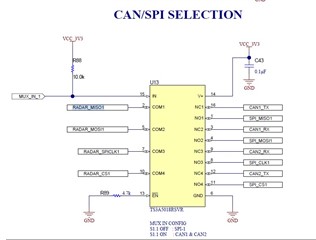
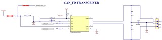
In this schematics , It is used GPIO_0 to control the CAN transceiver, is GPIO_ 0 should be used?

Or user can use other GPIO pin other than GPIO_0?

Regards,

A.Fujinaka

  • Fujinaka-san, 

    The CAN port can be accessed using the PIN-MUX. The correct balls are E14 and D13. Please use in conjunction with the correct position of S1.4.

    Thanks! 

  • Hello Brake,

    Thanks for your answer. My customer replied as follows.

    I want to understand which pin of IWR6843 needs to be connected to which component in order to set the can interface.

    1. In the linked schematic, GPIO_0 is connected to can_FD transceiver, but you mean , it should be E14 pin(SPIA_MISO) and D13 pin(SPIA_MOSI) Is this the intention that you need to connect radar_MISO1 and radar_MOSI1 in can/SPI selection below to TS3A5018?

    2.  GPIO_0 is connected to the can_FD transceiver, do I need only GPIO_0?

    3. . What is S1.4?

    Regards,

    A.Fujinaka

  • Fujinaka-san,

    1. In the linked schematic, GPIO_0 is connected to can_FD transceiver, but you mean , it should be E14 pin(SPIA_MISO) and D13 pin(SPIA_MOSI) Is this the intention that you need to connect radar_MISO1 and radar_MOSI1 in can/SPI selection below to TS3A5018?
    2.  GPIO_0 is connected to the can_FD transceiver, do I need only GPIO_0?

    No. GPIO_0 controls the mode of the CAN_FD transciever, but it doesn't carry data. The data signals will be propogated via the E14 (RADAR_MISO1) and D13 (RADAR_MOSI1) pins. You will need all three to utilize the CAN_FD transciever. 

    3. . What is S1.4?

    S1.4 is the switch that controls the MUX (U13) shown in your image above. It is the fourth switch in switch bank S1. 

    Thanks! 

    Blake