A related question is a question created from another question. When the related question is created, it will be automatically linked to the original question.
If you have a related question, please click the "Ask a related question" button in the top right corner. The newly created question will be automatically linked to this question.
Asking for the TMP401 remote sensor recommendation
Thank you for reaching out to us! I would happy to assist you here. We have varieties of temperature sensors available, but in order for me to choose the right temperature for your customer's application. I need your input of the following question.
1. What the target accuracy specs customer is looking for?
2. What is the target power supply range?
3. What type of application customer wants to measure the temperature of the system?
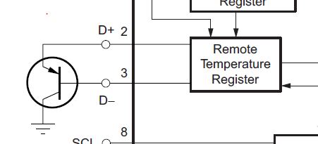
4. Could you please provide the application diagram?
Can you provide the suggested diode? Customer choose TMP401, any better suggestions?
Thanks,
SHH
1. What the target accuracy specs customer is looking for? ±1°C, spec is like TMP401. 2. What is the target power supply range? no required. it is not for portable device. 3. What type of application customer wants to measure the temperature of the system? panel backlight. 4. Could you please provide the application diagram? it is on the display monitor.
Page 14 of the datasheet recommends a 3904 type of remote diode. Other transistors can be used but that is most common. Page 14 also describes the type of transistors that can be use:
If a discrete transistor is used as the remote temperature sensor with the TMP401, the best accuracy can be
achieved by selecting the transistor according to the following criteria:
1. Base-emitter voltage > 0.25 V at 6 μA, at the highest sensed temperature.
2. Base-emitter voltage < 0.95 V at 120 μA, at the lowest sensed temperature.
3. Base resistance < 100 Ω.
4. Tight control of VBE characteristics indicated by small variations in hFE (that is, 50 to 150).
Based on these criteria, two recommended small-signal transistors are the 2N3904 (NPN) or 2N3906 (PNP).
If a transistor different than the 2N3904 is used then you should also get the n-factor specification of the device from the manufacturer so you can compensate the differences between that device and the 2N3904 as described in the datasheet on page 4:
The ideality factor (η) is a measured characteristic of a remote temperature sensor diode as compared to an
ideal diode. The ideality factor for the TMP401 is trimmed to be 1.008. For transistors whose ideality factor does not match the TMP401, Equation 1 can be used to calculate the temperature error. Note that for Equation 1 to be used correctly, actual temperature (°C) must be converted to Kelvin (°K).
Do they only require one remote diode sensor or multiple?
Customer would like to do small PCB for 3904 and place the small PCB on the remote back light panel side. The TMP401 place on the monitor main PCB board.
Then use the FFC cable to connect these two PCB board.
Here are the NPN and PNP part number MMBT3904LP and MMBT3906LP respectively. I normally used this on my board. Not sure if your customer is sensitive to cost instead of usingg FFC cable connects to the PCB. You might consider using flex circuit (FPC). With this, you do not need to connect FFC cable into the board.
Sorry for the delay. It looks like the transistor you picked is a 3904 type as the specs are identical to that of other manufacturers. It should work fine I believe. As a check though you should test it to make sure that the:
Base-emitter voltage > 0.25 V at 6 μA, at the highest sensed temperature.