


Other Parts Discussed in Thread: TMP112, TMP235, , ADS1113, LM73
Questions
General
Q1: Which temperature sensors are covered in this Forum?
Q2: Analog vs. Digital sensors, which one should I pick?
Device configuration
Q4: Which ADC should I use for the LMT70? Can I use the internal ADC of the MSP430?
Q6: How do I calculate the junction temperature of the LM73?
Q7: How do I calculate the average power consumption of the TMP112?
Best practices
Q8: What are best practices for measuring skin temperature?
Answers
Q1: Which temperature sensors are covered in this Forum?
Answer: This forum covers TI's Local and Remote Digital Temperature Sensors, Analog Temperature Sensors, Temperature Switches and Thermistors.
Q2: Analog vs. Digital sensors, which one should I pick?
Differences: A temperature sensor with an analog output, such as the TMP235, uses the transfer function to determine the temperature. A sensor with a digital output, such as the TMP112, does not require the system to know or program the internal analog transfer function to determine the temperature.
Usage: Systems with an analog sensor require an ADC to digitize its output and use a look-up-table to determine the temperature. Digital sensors already produce the digitized output of the measured temperature which can be read back over a digital interface (e.g. I2C).
Calibration requirements: For analog sensors, gain and offset of the ADC may need to be calibrated to achieve the desired system accuracy. System temperature accuracy is not guaranteed in datasheet as it is heavily dependent on the ADC reference error.
Digital sensors don’t need to be calibrated in order to get the accuracy that is guaranteed in the datasheet.
General guidance: As a general rule of thumb, digital temperature sensors are preferred in almost all cases due to lower system integration complexity and higher out-of-the-box performance. Exceptions where a digital sensor may cannot be used and an analog sensor is necessary include a lack of a suitable available digital interface bus or cost constraints
Q3: The datasheet specifies absolute temperature accuracy, but my system is calibrated so I only require relative accuracy. Can you provide tighter specifications for relative accuracy specifications?
Unfortunately, we cannot guarantee an accuracy other than what is written in the datasheet.
That said, our max specification covers a wide temperature range, and is guardbanded for measurement uncertainty.
Typically, the largest errors are at the edges of a specified temperature range. This is because the error function is either parabolic or s-shaped with regards to temperature. Most of our products are trimmed to zero error (to the best of our test equipment's ability) at room temperature.
When we set a max specification, we do so with the expectation that we will never produce a failing product. This is the purpose of guardbanding. The value listed in typical column is more representative of the performance we expect without guardbanding, but is not guaranteed.
Finally, we guarantee that the device will meet specification for the lifetime of the product. Prior to a new product launch, we subject a sample of devices to accelerated aging. This accelerated aging can simulate 10-20 years of use depending on the temperature of the application. All devices subjected to accelerated aging must also meet the max specification.
Q4: Which ADC should I use for the LMT70? Can I use the internal ADC of the MSP430?
Yes, it is possible to use the internal MSP430 ADC for this purpose. Note that the LMT70 is a high precision temperature sensor, and using the general purpose ADC of the MSP430 will limit the accuracy of the temperature measurement. For optimal measurement accuracy, it is recommended to pair the LMT70 with an external ADC such as the ADS1113.
Q6: How do I calculate the junction temperature of the LM73?
There are several parameters to take into account in order to find the LM73 self-heating. To determine the TJ of the LM73, you need to know the thermal resistance of the package (RθJA), the device power dissipation (Q) and the ambient temperature (TA). In the picture example below, the heat flows from the junction (TJ) to outside ambient (TA), it shows the independent thermal resistances that make up RθJA. The thermal resistance of the PCB depends on how many layers that you are going to use.
- Find Q, the maximum power dissipated by the device:
- Let’s assume that Vs (max)= 3.0V.
- The maximum current consumption according to the datasheet is 320 uA.
- To calculate the maximum power that the die is allowed to dissipate is Q = Vs(max) * Ips = 3.0*320 uA = 0.96 mW
- Then find ΔT, the temperature difference from the junction temperature and the ambient temperature
- With a 2-layer board and no airflow, the LM73 thermal resistance is RθJA = 186°C/W
- ∆T=(Q)(RθJA)=(0.96mW)(186°C/W)=0.179°C
- The junction temperature can then be calculated: TJ=∆T+ TA=0.179+25℃ = 25.179℃.
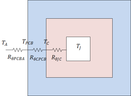
- Q is the power dissipated by the device.
- TJ is the junction temperature in the device.
- TC is the temperature at the case.
- TA is the temperature at ambient.
- TPCB is the temperature at PCB.
- RθJA is the device’s absolute thermal resistance from junction to ambient.
- RθJC is the device’s absolute thermal resistance from junction to case.
- RθCPCB is the case absolute thermal resistance from case to PCB.
- RθPCBA is the thermal resistance from PCB to ambient.
Q7: How do I calculate the average power consumption of the TMP112?
Datasheet sections 7.4.1 and 7.4.3 contain the information to calculate the average power consumption
Continuous sampling:
- Conversion: 26ms @ 40uA I2C read: 20us @ 40uA (current draw through the I2C pull-ups not included). Note that this time varies based on the system I2C speed.
- Quiescent current: 2.4uA
For example,
-
- if you sample at the slowest setting (0.25Hz), then the average current would be (0.25*26ms*40uA) + (0.25*20us*40uA) + ((1 - 0.25*26ms - 0.25*20us)*2.2uA) = 2.4 uA avg (excl. I2C pull-up resistor current)
- if you sample at the fastest setting (8Hz), then the average current would be (8*26ms*40uA) + (8*20us*40uA) + ((1 - 8*26ms - 8*20us)*2.2uA) = 10.1 uA avg (excl. I2C pull-up resistor current)
One shot mode
- In one shot mode, the calculation is similar to the one above, except:
- two I2C transactions per conversion are required (trigger and read)
- use shutdown current instead of quiescent current during idle times (500nA typ)
For example,
- if you sample at the at one Hz using one shot mode, then the average current would be (1*26ms*40uA) + (2*20us*40uA) + ((1 - 1*26ms - 2*20us)*500nA) = 1.5 uA avg (excl. I2C pull-up resistor current)
Q8: What are best practices for measuring skin temperature?
Please refer to the following material for information:
-
The Human Skin Temperature Sensing for Wearable Applications Reference Design will show how to use the LMT70 temperature sensor to measure human skin temperature in a wearable device such as a smart watch or a fitness tracker
- The slides from TI's Skin Temperature Measurement Webinar show various methods of measuring skin and body temperature using the TMP112 and the LMT70.

