Other Parts Discussed in Thread: IWR6843
I was hoping to get some clarification on the ideal impedance for the LVDS traces with the IWR6843.
In the Hardware checklist, it's mentioned that they should be "routed as pairs of 50 ohm to GND to 50 ohm". I'm not sure I understand what that means? Are we talking about even, odd, differential, or common mode impedance here?
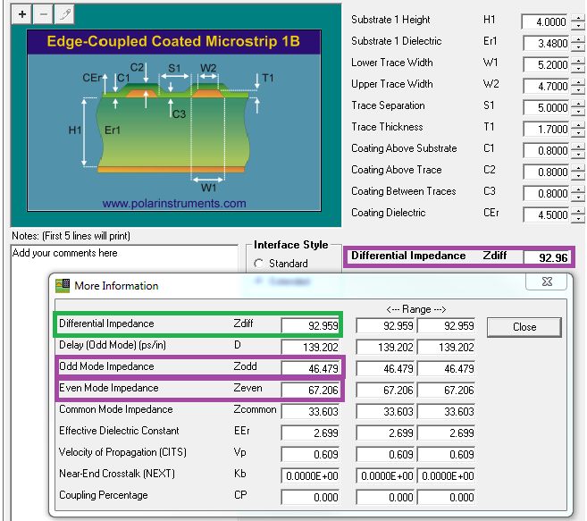
When running Polar's 2D field solver tool with the ISK's parameters, a differential impedance of 93ohm is calculated, with 46.5ohm odd mode impedance. Slight modification of the trace width and spacing can give 100ohm and 50ohm, respectively, for differential and odd impedance.
Could you clarify what the 50 ohm is referring to, and also whether those values calculated in Polar are valid? assuming the 50ohm is supposed to be odd mode impedance, where might the discrepancy be coming from?