This thread has been locked.

If you have a related question, please click the "Ask a related question" button in the top right corner. The newly created question will be automatically linked to this question.

FDC2214EVM: Using OPA322 as a signal conditioning or as an actively driven shield for FDC2214EVM's input

Part Number: FDC2214EVM
Other Parts Discussed in Thread: OPA322, , FDC2214, FDC1004

Hi,

I am trying to use OPA322 as a signal conditioning or as an actively driven shield for FDC2214EVM's input, and have run into trouble. The overall frequency became over 40Mhz, which halted the channel's measurement/response. 

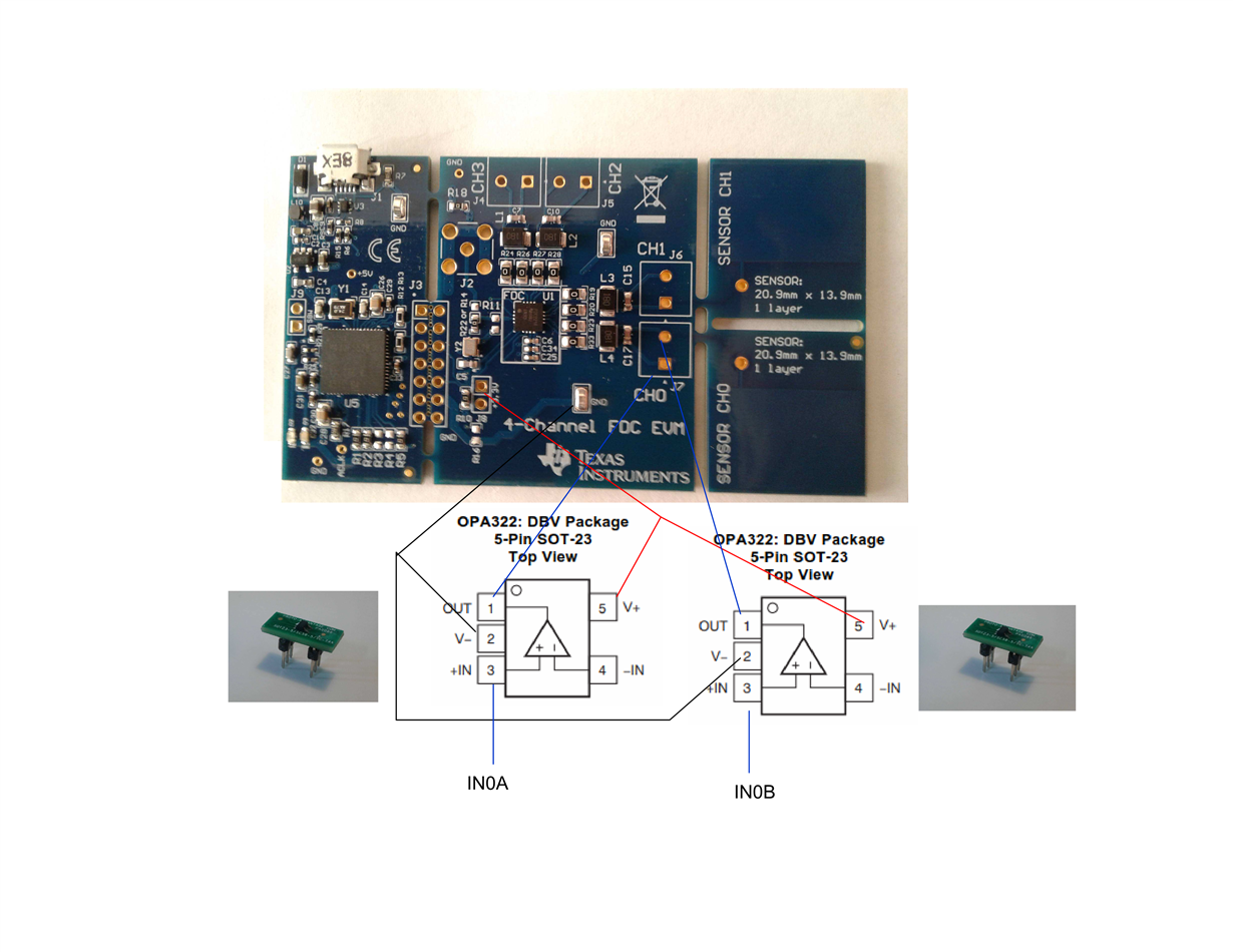
The OPA was soldered on an adaptive board,   https://www.digikey.ca/product-detail/en/PA0086/PA0086-ND/5014711/?itemSeq=293753807  for testing, attached is an illustration of my connection.

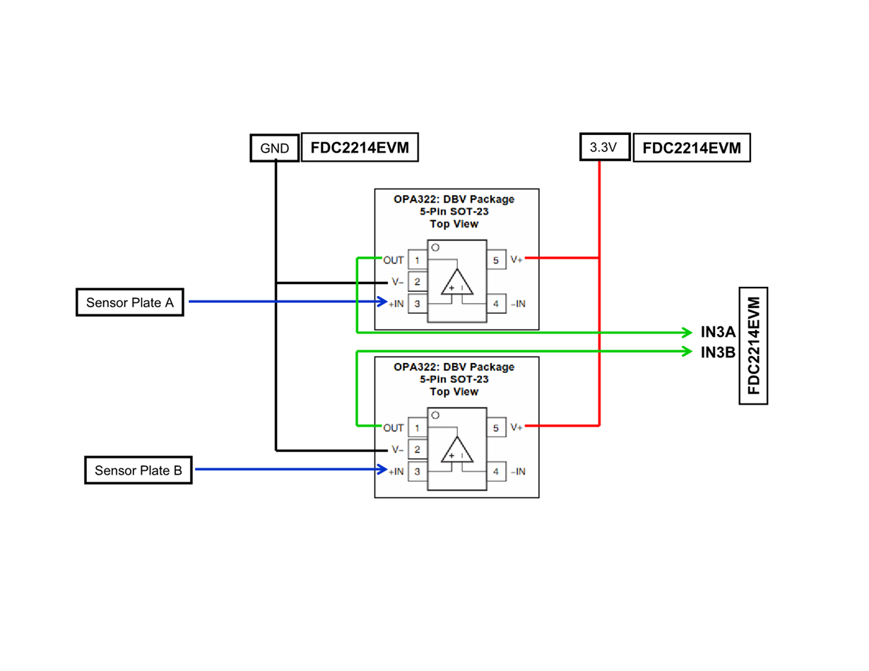
My differential sensor plates A and B, having capacitance 60-80 pF, are connected to PIN3 (+IN) of the OPA; The OPA's outputs (PIN1) are connected to the input channel 0 of the FDC, IN0A and IN0B; Power supply for the OPAs (PIN5, V+)  is taken from the FDC's 3.3V at J8;  PIN2 (V-) of the OPA is connected to a ground on the FDC board. 

I also tried to use just one OPA for one sensor plate, the overall frequency dropped to 26-29MHz for different OPA322s, I tried 4 of the OPA322 separately, capacitance reading precision were worse than other channels using input deglitch filter 33MHz. 

OPA322 is an amplifier with gain =1, it should not have such a big impact on input frequency.

Can someone help with the issue?

Regards,

Gu


  • Can you draw a quick schematic for the final configuration? Have you broken off the EVM sensor that is already on channel 0?

    If you are putting a buffer in-between the capacitor and the FDC2214, then the FDC2214 will be unable to drive the LC tank and therefore sense the frequency. To do an active shield, you should be using the op amp to generate the shield signal. The sense signal should still be connected directly to the FDC device.

  • Hi Clancy,

    Thank you for your reply. I am including a drawing showing my connection. I thought to use the OPA as front signal conditioning to improve measurement precision or for noise reduction.  

    I have not broken the FDC2214EVM yet, I also tried it on channel 3 (IN3A and IN3B) as illustrated in the drawing, the result is the same as on channel 0.  

    I do not quite understand your suggestion about using the OPA to generate a shield signa. Could you please provide some details?

    Regards,

    Gu 

  • Gu,

    I don't think that you can leave -IN floating. Either way though, I don't think this will work. The FDC2214 reacts to the capacitance changes in the sensor plates. It can't do that if there is a buffer in-between.

    We have shield signals on the FDC1004 if you are curious what I was referring to. We don't have a recommended circuit to generate similar signals for the FDC2214 (although you could probably figure out something with some op amps), and it doesn't sound like that is what you need anyways.

  • Hi Clancy,

    Thanks for your comments. I think that I am not able to figure out the way as the FDC1004's actively driven shield for the FDC2214.

    Gu

  • Gu,

    What are you trying to do exactly? I don't think that adding op amps for signal conditioning will help with this device. Is there a specific performance problem that you are trying to solve?

  • Hi Clancy,

    Currently, the FDC2214EVM can achieved  0.002 pF precision, I am wondering if I can bring it under 0.001pF. 

    Gu,

  • Gu,

    Signal conditioning is not the way to do this. This app note discusses resolution in terms of the LDC devices, but the LDC161x advice is the same for the FDC221x. You'll notice that the best ways to reduce the noise floor are to increase the RCOUNT setting and use an external oscillator.

    http://www.ti.com/lit/pdf/snoa944/

  • Hi Clancy,

    The link you provided is an excellent application note for me. Definitely, it will help me to go on a right direction and eliminate some possible wrong tries.   

    The note suggests that Rcount and frequency ratio of senor-to-reference  are the two most important factors contributing to the effective resolution. The Rcount can be set to 0XFFFF regardless. So the frequency ratio of senor-to-reference should be my focus. I already started to search for a better oscillator before receiving your link to the snoa944, but paid attention to its frequency stability and jilter at a fixed 40 MHz. Now, I think that I should find a proper reference frequency first, and then pay attention to its frequency stability and jilter.

    My sensor's base frequency is at 3.5MHz around, frequency change is very limited in a measurement, but is my interest, hence I need a high measurement precision or high effective resolution. Based on the snoa944 note, a frequency ratio of senor-to-reference, 0.025, is suggested, this leads me to think of 1) using a 140 MHz off-board oscillator instead of the 40 MHz on-board oscillator, then to look for the stability and jilter specs; 2) reducing my sensor's base frequency by adding a capacitor so that frequency ratio of senor-to-reference can be close to 0.025; 3) combining 1) and 2) by using a 100MHz reference oscillator and adding a capacitor as well. 

    Could you please comment on my understanding and the approach I am going to take?

    Best regards,

    Gu

  • The only thing you are missing is that the maximum external oscillator is 40MHz. Look at the fCLKIN specification. And if you look at table 1, you will see that we recommend a maximum of 35MHz if you are only using a single channel. To achieve the best performance, we usually recommend using the highest frequency reference oscillator possible.

  • Hi Clancy,

    Yes, I missed the max limit in frequency of the FDC2214. thank you for pointing it out. I have placed an order for 40 MHz-oscillators that have better stability and jitter than the one on board.

    Best regards,