This thread has been locked.

If you have a related question, please click the "Ask a related question" button in the top right corner. The newly created question will be automatically linked to this question.

IWR6843: filter order/frequency response

Part Number: IWR6843

Hello,

Is there any more information on the filter orders of the highpass/lowpass filters used in the IF stage?

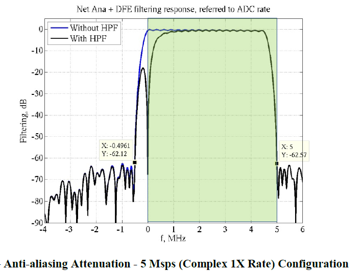
Are there any plots for the frequency response?

Thanks and regards,

Carsten

  • Hi Carsten,

    I've asked an expert to look into this and we should have an answer for you in the next few days.


    Cheers,

    Akash

  • Hi Carsten,

        Could you please review below E2E thread? Below thread discuss frequency response highpass/lowpass filters used in the IF stage.

    https://e2e.ti.com/support/sensors/f/1023/t/747457

    Thanks and regards,

    CHETHAN KUMAR Y.B.

  • This is not at all the answer to what he asked.  A digital low-pass can not prevent aliasing.  What he (and I) am looking for are the characteristics of the ANALOG low-pass filter, namely:

    • Is the corner frequency of the low-pass filter adjustable?
    • If it is adjustable, what are the possible values?
    • What type of filter is it?  (Butterworth, Chebyschev, etc.)
    • What order is the filter? (1st, 2nd, 3rd, etc.)

    It's pretty wild that none of this information is the datasheet or technical reference manual, as they are critical system design parameters. 

  • Hello Barrett,

     Yes, filter corner frequency is adjustable, anti aliasing filter cutoff frequency is in a linear relationship with the ADC sampling frequency. The ADC is a sigma-delta ADC. The sigma-delta ADC output is processed by a chain of decimation/re-sampler stages. The configuration of the decimation stages and re-sampler stages are automatically managed by TI built-in firmware and the customer can directly program the required final desired output sampling rate via the Profile Configuration API. Sampling rate and IF bandwidth cannot be decoupled.  

    The filtering performed by the base-band chain is targeted to provide:

    (a) Under +/- 0.5 dB pass-band ripple/droop, and

    (b) Better than 60 dB anti-aliasing attenuation for any frequency that can alias back into the pass-band. This is part of sigma delta modulator chain. 

    As an illustration, below presents the effective response for the 4.5 MHz max beat frequency use-case. The output sampling rate is the optimum with 90% bandwidth utilization (4.5 out of 5 MHz). The effective HPF + digital low pass filtering response is shown below. The pass-band in this example is 0 to 4.5 MHz, and the aliasing bands lie outside -0.5 MHz and +5.0 MHz The pass-band ripple/droop is under +/- 0.5 dB, while the anti-aliasing attenuation is greater than 60 dB, starting at 5 MHz In Figure, the green patch represents the frequencies visible at the final output rate.

    Thanks and regards,

    CHETHAN KUMAR Y.B.