This thread has been locked.

If you have a related question, please click the "Ask a related question" button in the top right corner. The newly created question will be automatically linked to this question.

AWR1642: AWR1642: DSP does not detect interrupt from MMIC

Part Number: AWR1642
Other Parts Discussed in Thread: SYSBIOS

Hello,

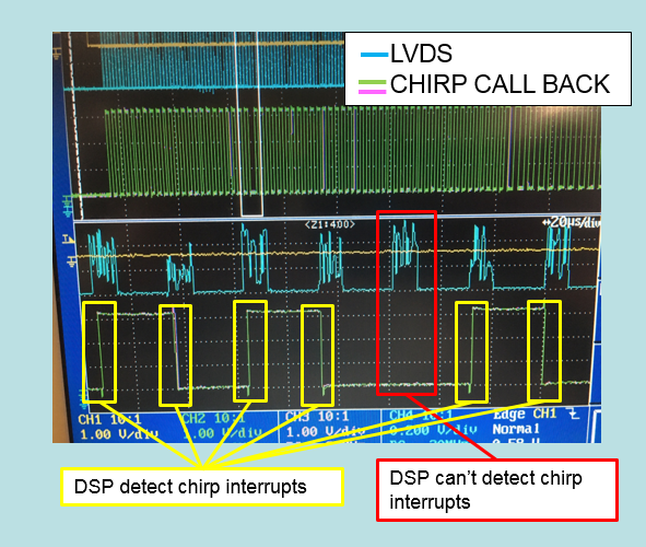
When debugging the timing of an LVDS and DSP chirp interrupt using an oscilloscope, the DSP may not detect the chirp interrupt.
*DSP is processing previousframe data.(Tracking etc.)

I think the MMIC is working properly because the hard-triggered LVDS is working properly.
So, I think there is a problem with SYS / BIOS.

Does the SYS/BIOS become less responsive to interrupts while the DSP is doing something?
Or are there other factors that can make the SYS/BIOS less responsive?

The environment is as follows.
SDK: 2.0.0.4
SYS / BIOS: 6.53.2.0
XDC: 3.50.4.43


* LVDS operates with a hard trigger and displays the Tx Hi waveform.
* The CHIRP CALL BACK (green and red) is inverted each time the DSP detects a chirp interrupt.

  • Hi,

    You need to provide more information about the setup of this experiment.

    How do you probe these two interrupts? I guess you are controlling one of GPIO from DSP.

    When you see chirp interrupt (GPIO toggle) missing, within DSS also does it have a mismatch in chirp Interrupt count?

    Regards,

    Jitendra

  • Hello Jitendra,

    The answers to your questions are listed below.

    〇How do you probe these two interrupts? I guess you are controlling one of GPIO from DSP.

         Yes. 

        I operate GIO from DSP and switch High/Low of GPIO.

     GPIO control is switching GPIO_0 High / Low every time the Chirp callback function is called. In addition, every time the callback function completes, it switches High / Low of GPIO_1.

    〇When you see chirp interrupt (GPIO toggle) missing, within DSS also does it have a mismatch in chirp Interrupt count?
    →Yes.

       If the chirp interrupt is missing, the chirp count in DSS is less than the set value.

    Thanks and regards,

    Takahashi.

  • I somewhat understood your code on DSS. Do you observe missing chirp interrupt even without GPIO control code? As with default mmw demo application, we don't observe any missing chirp interrupt.

    You can try writing below register-value from MSS, which connects ADC_VALID to GPIO_0 line.

    REG32_write(0xFFFFEBF8,0x83E70B13)
    REG32_write(0xFFFFEBFC,0x95A4F1E0)
    REG32_write(0xFFFFE260,0x6101)
    REG32_write(0xFFFFE270,0x30)
    REG32_write(0xFFFFEA04,0x44)
    REG32_write(0xFFFFEBF8,0x0)
    REG32_write(0xFFFFEBFC,0x0)

    With this change, you don't need to toggle GPIO from DSS as it is now connected to ADC_VALID interrupt line. ADC_VALID is same as chirp-interrupt to DSS.

    Regards,

    Jitendra

  • Hello Jitendra,

    I tried the content in the your reply.
    The result was that MSS detected an interrupt, but DSS did not.

    From this result, it seems that interrupts are temporarily disabled in the DSS BIOS.
    Do you have any idea why the interrupt stops?

    Thanks and regards,

    Takahashi

  • Hi Takahashi-San,

    I was suggesting to disable GPIO control from DSS and enable above mentioned register writes from MSS which does the connection of ADC_VALID to GPIO_0 pin. So externally you can see the chirp-interrupts when you probe on GPIO_0 pin.

    Now as per your latest picture, what is green color plot means? Is that when DSS controls/toggles GPIO? Which pin you have probed for MSS and DSS plot displayed in this picture?

    On the other hand DSS should not miss any chirp interrupt internally on its core to do the signal processing, as mmw demo gives the reference where it never misses any chirp interrupt while doing the processing running sysbios.

    Regards,

    Jitendra

  • Hello Jitendra,

    The green waveform is the GPIO_21 waveform controlled from the DSS.
    The control contents of this GPIO are the same as before, switching High / Low each time the chirp callback function is called.

    The reason for controlling the GPIO from the DSS is that you do not know when the DSS misses the chirp interrupt. In other words, if you do not monitor the DSS, you will not know where you missed the interrupt.

    The red waveform is the waveform measured on GPIO_0 using the content of your reply. Therefore, I recognize that this waveform is synchronized with the interrupt detected by MSS.

    In your reply, "DSS should not miss any chirp interrupt internally on its core to do the signal processing" means monitoring the counter inside DSS?

    Thanks and regards,
    Takahashi

  • Hello Jitendra,

    The measurement was performed with the following settings.

    -All GPIO control from DSS is invalid.

    -Set to synchronize GPIO_0 with ADC_VALID from MSS.

    As a result, GPIO_0 had no problem, but the DSS chirp interrupt counter is less than the specified number. Therefore, it is considered that the DSS missed the interrupt.

    Thanks and regards,
    Takahashi

  • Hello Takahashi-san,

    Is it possible to do assert in DSS and send failure log over UART/CAN outside of chip when it misses any chirp interrupt? With this setup, could you try the experiment without any JTAG connection?

    As in mmw demo of mmwave SDK, DSS has the check for missing any chirp interrupt while it does the signal processing. And with default mmw demo I don't see any of missing chirp interrupt at DSS end.

    You need to check if sufficient chirp idle time is configured to RadarSS in rlSetProfileConfig API. DSS should complete the processing (1-D FFT : inter chirp time) within this time so it will be free to honor the next chirp interrupt when it arrives.

    In the DSS application any of chirp/frame interrupt is set to higher priority interrupt so even DSS is busy in some task, it will switch to interrupt context (chirp interrupt) when it arrives.

    Regards,

    Jitendra

  • Hello Jitendra

    This occurred even when the software was written to the ROM and started.

    And It seems that your perception is different from my perception. So let me check the contents.
     The software we use is a modified version of the demo software.
     The MMIC does not start at a fixed timing, but starts every time with a trigger from ARM(timer event or external trigger received by ARM).
     This missed chirp interrupt occurred when a problem occurred with an external trigger.
     The condition is
      1. 1D-FFT is completed, that is, chirp interrupt processing is completed normally.
      2.1 External trigger is activated by mistake during interFrameProccesing () after 1D-FFT, and MMIC is activated.
     This problem occurs when this above condition is met.

    I realize that chirp interrupts have a higher priority than spawned tasks.
    So, what I want to know is if there is something in the DSP program that delays interrupts.
    For example
    ・Heavy stack load
    ・ Interruption is delayed when using specific assembler code
    ・Interruption stops during exception processing.
    etc.

    Thanks and regards,
    Takahashi

  • Hello Takahashi-san,

    What I understood that you are trying to trigger the frame with an external pulse and you have set triggerSelect option to (0x0002 HWTRIGGER) in rlSetFrameConfig API.

    So now RadarSS which honors the HW pulse won't trigger next frame if any pulse arrives during any current frame is running.

    i.e. Frame consists of multiple chirps and later frame-idle time; new HW pulse must be given only after the frame-idle time.

    If any next pulse is given within this frame time that it won't trigger any new frame (or chirp). so expecting DSP to receive chirp interrupt is out of scope.

    Now you need to check what is timing of External trigger pulse with respect to frame timing.

    Regards,

    Jitendra

  • Hello Jitendra,

    BSS is operated by soft trigger.
    External trigger is received by MSS. MSS calls rlSensorStart () when receiving an external trigger.
    So, rlSetFrameConfig API is set to soft trigger.

    The external  trigger timing when a problem occurs is later than the frame time set in BSS.
    * The frame time set in BSS differs from the DSS processing cycle time. The DSS frame processing time is set longer than the BSS frame time.
    Therefore, BSS detects the soft trigger from MSS, and the radio wave emits Sample and Chirp as specified.

    This is consistent with the result that the ADC_VALID measured in the previous MSS is normal, but the DSS missed the chirp interrupt.

    Thanks and regards,
    Takahashi

  • Hello Takahashi-san,

    • Could you compare the DSS application implementation with mmw demo DSS application for interrupt (frame/chirp) handler implementation?
    • As you are using single frame setting in rlSetFrameConfig and do the frame trigger (rlSensorStart) from MSS (external trigger).
    • How about using continuous framing mode instead of HW trigger (from MSS rlSensorStart), i.e. infinite no. of frame is in rlSetFrameConfig API? Do you see same behaviour with this setting?
    • In the DSS application do you wait for frame start or end async event message before re-triggerring next frame? if yes then remove that wait on DSS application.
    • And keep chirpinterrupt handler function with minimal code in it.
    • In the DSS application if you have any while wait loop then make sure that you have Task_sleep within while loop so task context switch happens when interrupt arrives; ideally interrupt context is highest of task priority so it should switch to interrupt handler.

    Regards,

    Jitendra

  • Hello Jitendra,

    I have a question about:
    " In the DSS application if you have any while wait loop then make sure that you have Task_sleep within while loop so task context switch happens when interrupt arrives; ideally interrupt context is highest of task priority so it should switch to interrupt handler. ”

    Questions:

    • Does it mean that if there is no TaskSleep () in the while loop, there will be a delay in switching contexts?
    • Is the processing priority in the while loop temporarily increased to speed up the processing?
    • If the above is yes, does it occur not only in the while loop but also in the for loop?

    Thanks and regards,
    Takahashi.

  • * TaskSleep is mainly required to switch to another concurrent running task (lower or higher) if application is blocked in some infinite wait while loop. Else sysbios will take care of switching the context itself it observes some idle task.

    * As per mmw demo, task which does the processing is already the highest. So it doesn't affect the processing speed from that task.

    * TaskSleep within blocked loop is applicable for for and while both.

    Let me just recap this issue-

    you were saying that MSS sends extra pulse to trigger sensorStart by mistake, when it sends that signal what is DSS state? Is it doing 2-D or 3-D FFT or other processing during that time?

    Ideally New frame should start only after last frame processing is fully done.

    Is there any specific purpose to to trigger sensorstart event but why can't you use infinite frame to avoid trigger from MSS (invoking sensorStart API).

    And other thing mmw demo does while invoking sensor start that it first sync with DSS (means sends one mailbox message to DSS so it does all the preperation first, then only MSS sends SensorStart message to RadarSS over mailbox.

    You need to consider the DSS status (if it should not be doing last frame processing) and preperation timing for current frame trigger to avoid this type of error.

    Regards,

    Jitendra

  • Hello Jitendra,

    The answer is described below.

    Your question

    • "You were saying that MSS sends extra pulse to trigger sensorStart by mistake, when it sends that signal what is DSS state? Is it doing 2-D or 3-D FFT or other processing during that time? ''

    Answer

    • Yes. DSS is processing the data. The processing being performed is processing such as tracking and grouping.

    Your question

    • "Is there any specific purpose to to trigger sensorstart event but why can't you use infinite frame to avoid trigger from MSS (invoking sensorStart API). ''

    Answer

    • The inifinite frame cannot be used due to the system design.


    My questions:

    • Why is Task_Sleep required for task switching regardless of priority? Does the BIOS sometimes disable interrupts?
    • Is "preperation timing for current frame trigger" the timing when DSS frame processing is completed?
    • How do I switch an interrupt function from context to handler?

    Thanks and regards,

    Takahashi

  • Hello Takahashi-san,

    Ideally new frame trigger should happen only after all the processing of last frame is done else DSP won't be able to do the processing of chirp from next frame (as it is busy with last frame processing). So you need to make sure that next sensorStart trigger must arrive only after the last frame processing is over.

    * BIOS doesn't disable the interrupt b default till application disables it.

    * Yes, it needs to trigger ONLY WHEN last frame processing is completed.

    * Ideally interrupt context is the highest priority so it should switch to that handler independent of Task priority.

    I would request to follow the above condition to follow the timing constraint. 

    In mmw demo I have checked almost same scenario but I have set long frame count but set frame periodicity very short, so next frame interrupt arrives before DSP is completed last frame processing. So in that case it hit the next chirp interrupt handler and hit the ASSERT condition (due to last frame processing is not over).

    Regards,

    Jitendra