This thread has been locked.

If you have a related question, please click the "Ask a related question" button in the top right corner. The newly created question will be automatically linked to this question.

PGA460-Q1: Using 2 Transciever (both transmitter and receiver feature in a sensor) with PGA460-Q1

Part Number: PGA460-Q1
Other Parts Discussed in Thread: PGA460, ENERGIA, PGA460PSM-EVM, TS12A12511, TMUX6119, TMUX1121, TMUX1122, SN74LVC1G66

Hello,

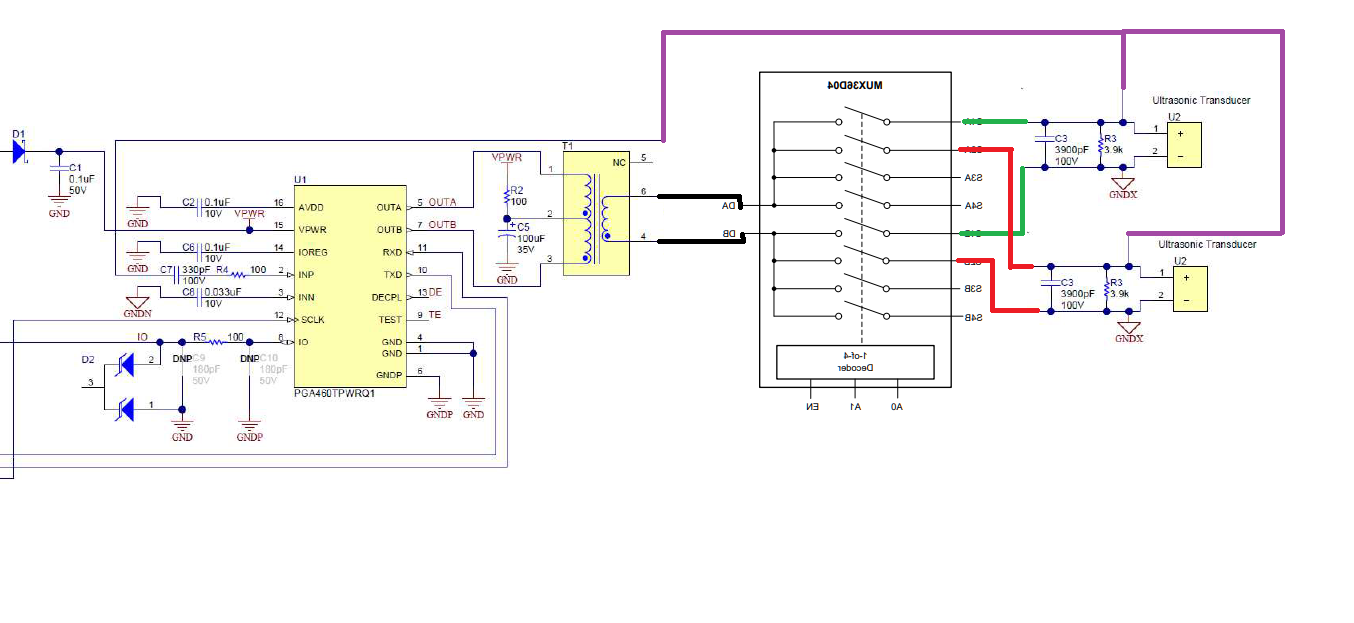
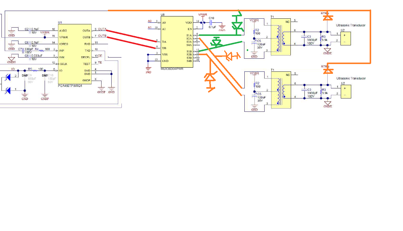
I wanna use 2 transciever sensor that synchronous each other with PGA460-Q1. How can I do? Do I need 2 PGA460-Q1 or can I make this 1 PGA460-Q1? 

Best regards.

  • Hi Lacin,

    The PGA460 is a single channel device, so you will need to pair one PGA460 with one transceiver. This means you will need two separate PGA460 modules that you can then connect to the same UART / SPI / OWU bus to synchronize time-of-flight commands. The PGA460 includes broadcast commands (see datasheet Table 3), which are intended for the purpose of synchronization.

    I have also discussed some special case synchronization routines in the following app report: PGA460 Array of Ultrasonic Transducers for Triangulation and Tracking 

    There is also the option of multiplexing or node sharing multiple transducers with one PGA460, but you will typically be operating one transducer at a time rather than all simultaneously in this configuration: https://e2e.ti.com/support/sensors/f/1023/t/603257

  • Hi Akeem,

    Thanks for your reply and two different solution you suggested. So, which one is better? I need 2 different transceiver that see 2 different angles and I need to know which is nearer position to wall. If I will do it with MUX, how shoult I write the code? Could you send me example code? And how did you controlled PGA460 which you sent me? I think you connect external MSP or PIC or Arduino module because I couldn't see any microcontroller. Am I wrong?

    Or if I will do it with 2 different PGA460, should I use to Triangulation code that given? And also I need the cheapest and the easiest solution :)

    See you!! :))

  • Hi Lacin,

    For a two sensor solution, the cost and complexity is about the same between the two-PGA460 option versus one-PGA460 multiplexing option. It is only when you need 3 or more transducers that the multiplex solution becomes the cheaper option.

    As far as programming complexity is concerned, the GetDistance.ino Energia sketch for the PGA460 would only need to be updated to include a GPIO control to toggle and set the active multiplex channel. You'll notice the MUX36 device in the multiplexing example uses A0 and A1 digital pins to control the active channel.

    If you are going to use two independent PGA460 devices, then you can refer to the BusDemo.ino Energia sketch for the PGA460, which is currently compatible with a UART bus. The two PGA460 devices on the bus will have different UART_ADDR values, so you can independently control and communicate to one PGA460 at a time based on the UART_ADDR of the master command field byte of the UART frame.

    Either option will work for your application.

  • Hi again,

    I think, I wanna use solution which is include mux. Should I change GetDistance.ino as follows?

    void loop() { // put your main code here, to run repeatedly


    // -+-+-+-+-+-+-+-+-+-+- PRESET 1 (SHORT RANGE) MEASUREMENT -+-+-+-+-+-+-+-+-+-+- //
    objectDetected = false; // Initialize object detected flag to false
    ussc.ultrasonicCmd(0,numOfObj); // run preset 1 (short distance) burst+listen for 1 object

    int Select_US = 1;
    if(Select_US = 1)
    {

    digitalWrite(A0,LOW); digitalWrite(A1,LOW); // Sensor1 connected S1A

    ussc.pullUltrasonicMeasResult(demoMode); // Pull Ultrasonic Measurement Result
    for (byte i=0; i<numOfObj; i++)

    {
    // Log uUltrasonic Measurement Result: Obj1: 0=Distance(m), 1=Width, 2=Amplitude; Obj2: 3=Distance(m), 4=Width, 5=Amplitude; etc.;
    distance1 = ussc.printUltrasonicMeasResult(0+(i*3));

    delay(commandDelay);

    Select_US = 2; 

    }

    if(Select_US = 2)

    {

    digitalWrite(A0,HIGH); digitalWrite(A1,LOW); // Sensor2 connected S2A

    ussc.pullUltrasonicMeasResult(demoMode); // Pull Ultrasonic Measurement Result

    for (byte i=0; i<numOfObj; i++)


    // Log uUltrasonic Measurement Result: Obj1: 0=Distance(m), 1=Width, 2=Amplitude; Obj2: 3=Distance(m), 4=Width, 5=Amplitude; etc.;
    distance2 = ussc.printUltrasonicMeasResult(0+(i*3)); 

    delay(commandDelay);

    Select_US = 1; 

    }

    if(distance1<=distance2) {distance=distance1;}

    else{distance=distance2;}

    if (distance > minDistLim && distance < 11.2) // turn on DS1_LED if object is above minDistLim
    {
    ussc.toggleLEDs(HIGH,LOW,LOW);
    Serial.print("P1 Obj"); Serial.print(i+1); Serial.print(" Distance (m): "); Serial.println(distance);
    objectDetected = true;
    }
    }

    // -+-+-+-+-+-+-+-+-+-+- PRESET 2 (LONG RANGE) MEASUREMENT -+-+-+-+-+-+-+-+-+-+- //
    if(objectDetected == false || alwaysLong == true) // If no preset 1 (short distance) measurement result, switch to Preset 2 B+L command
    {
    ussc.ultrasonicCmd(1,numOfObj); // run preset 2 (long distance) burst+listen for 1 object

    if(Select_US = 1)
    {

    digitalWrite(A0,LOW); digitalWrite(A1,LOW); // Sensor1 connected S1A

    ussc.pullUltrasonicMeasResult(demoMode); // Pull Ultrasonic Measurement Result

    for (byte i=0; i<numOfObj; i++)


    // Log uUltrasonic Measurement Result: Obj1: 0=Distance(m), 1=Width, 2=Amplitude; Obj2: 3=Distance(m), 4=Width, 5=Amplitude; etc.;
    distance1 = ussc.printUltrasonicMeasResult(0+(i*3)); 

    delay(commandDelay);

    Select_US = 2; 

    }

    if(Select_US = 2)

    {

    digitalWrite(A0,HIGH); digitalWrite(A1,LOW); // Sensor2 connected S2A

    ussc.pullUltrasonicMeasResult(demoMode); // Pull Ultrasonic Measurement Result

    for (byte i=0; i<numOfObj; i++)


    // Log uUltrasonic Measurement Result: Obj1: 0=Distance(m), 1=Width, 2=Amplitude; Obj2: 3=Distance(m), 4=Width, 5=Amplitude; etc.;
    distance2 = ussc.printUltrasonicMeasResult(0+(i*3)); 

    delay(commandDelay);

    Select_US = 1; 

    }

    if(distance1<=distance2) {distance=distance1;}

    else{distance=distance2;}

    delay(commandDelay);

    if (distance < 1 && distance > minDistLim) // turn on DS1_LED and F_DIAG_LED if object is within 1m
    {
    ussc.toggleLEDs(HIGH,LOW,LOW);
    Serial.print("P2 Obj"); Serial.print(i+1); Serial.print(" Distance (m): "); Serial.println(distance);
    objectDetected = true;
    }
    else if (distance < 3 && distance >= 1) // turn on DS1_LED and F_DIAG_LED if object is within 3m
    {
    ussc.toggleLEDs(HIGH,HIGH,LOW);
    Serial.print("P2 Obj"); Serial.print(i+1); Serial.print(" Distance (m): "); Serial.println(distance);
    objectDetected = true;
    }
    else if (distance >= 3 && distance < 11.2) // turn on DS1_LED, F_DIAG_LED, and V_DIAG_LED if object is greater than 3m
    {
    ussc.toggleLEDs(HIGH,HIGH,HIGH);
    Serial.print("P2 Obj"); Serial.print(i+1); Serial.print(" Distance (m): "); Serial.println(distance);
    objectDetected = true;
    }
    else if (distance == 0 && commMode!=1) // turn off all LEDs if no object detected
    {
    ussc.toggleLEDs(LOW,LOW,LOW);
    //Serial.print("Error reading measurement results..."); //Serial.println(distance);
    }
    else //(distance > 11.2 && distance < minDistLim) // turn off all LEDs if no object detected or below minimum distance limit
    {
    if (i == numOfObj-1 && objectDetected == false)
    {
    ussc.toggleLEDs(LOW,LOW,LOW);
    Serial.println("No object...");
    }
    }
    }
    }

    If I write code like this, do I have a time-related problem, such as detecting the distance late? And here "https://e2e.ti.com/support/sensors/f/1023/t/603257 " you used mosfet instead of transformer. Which is much better? Transcievers which is in your circuit are working with square wave, not sine wave. I have transcievers which is working with sine wave. Can I use these with this mux? Can this mux works with sine wave? If it works, how can I connect transformer and mux?

  • So, can I connect this as above =) Sorry for this bad picture, I did it with paint and this is a very amateur work.

  • Hi Lacin,

    The multiplexing solution in linked to is currently designed for the direct driver mode only (transformer-less). The circuit as you have drawn has not been tested, and runs the risk of exceeding the 36V rating of the MUX device unless you keep the center-tap voltage and driver current limit setting low. Theoretically, you would also need to drive the transformer in a single-ended mode and add a forward diode to the MUX output pins to block the negative voltage swing from the transducers. Also, the receiver path (purple) should be at pin DA. The way you have drawn the purple as-is has the two transducers in parallel to each other, which would excite both and defeat the purpose of the mux.

    Personally, I think there is too much risk using a transformer driver and mux combo. Remember, transformer drivers are typically used to generate hundreds of volts at a closed-face transducer to detect long range objects. It will not be easy to find a high-voltage yet low-cost mux if your goal is to keep the solution cost. If you intend on using a transformer driver, your only option is to use two independent PGA460 devices.

    If you are to change to a direct driver for muxing, you can also use a different mux part number (TMUX6119 for up to 18V driver support) since you only have two transducers. Consider using a Single-Pole Double-Throw to save on cost/complexity, and only require the use of one GPIO. Your implementation of the GPIO switch is on the right track.

    If you need clarification on the difference between a transformer driver and the direct driver, see section "3.3 Driver Selection" of https://www.ti.com/lit/pdf/slaa732.

  • Hi Akeem,

    Thanks for reply. But how about the code? I think, you didn't see my previous message. If you check it, I will be happy.

    1. And about the transformer, I'm not sure that is big mistake. I will use 7.7V supply for PGA460 and I guess the transformer has 1:1 ratio. (I mean it doesnt increase the voltage). Is it still a problem to make a connection like this?
    2. Or can I use this circuit with transceiver that is using with sine wave? "https://e2e.ti.com/support/sensors/f/1023/t/603257" I need to detect for 0.3 - 4 meters.
    3. And about purple line, when transformer uses, in PGA460PSM-EVM schematic, RTRN line connected to INNP pin.
    4. Another issue, if I use 2 different PGA460-Q1, how should I connect to same microcontroller? Should microcontroller has 2 uart channel or is one-channel enough? If one-channel UART is enough for our project, how shoult I connect PGA460s with microcontroller? Will the signals I send and receive not collide? Can you send a schematic as an example of the connections?

  • Lacin,

    Responding to your questions:

    Regarding the code, I said "Your implementation of the GPIO switch is on the right track." I will not be able run and verify your code since I will not have your multiplexing hardware solution.

    1. The transformer on the PGA460PSM-EVM is the Wurth 750317161 push-pull transformer, which has a turns ratio of 1:1:8.42. This means with a 7.7V center tap, you'd generate a maximum of +/-65V at the secondary. This will violate the maximum rating and damage the multiplexer, which is why I do not recommend pairing a transformer driver with a multiplexer.
    2. I do recommend that you use the direct driver circuit as I have demonstrated in the E2E mux article ( https://e2e.ti.com/support/sensors/f/1023/t/603257 ). You can use any transducer with this mux solution, but keep in mind that the maximum voltage you can generate in the direct driver mode is 30V. If your application does not need to be water proof or dirt proof, then you can use the open-top transducers shown in the E2E mux article. Here is a list of transducer part numbers to explore: PGA460 Transducer & Transformer Listing
    3. Yes, the purple line is the RTRN line. Note, the RTRN line is node shared with the excitation pin of the transformer because this is a mono-static configuration (driver and receiver are node shared). In order to isolate which transducer you are getting the information from in the mux solution, you should not have the RTRN line connected to both transducers, which is why RTRN needs to be connected to the common side of the mux.
    4. When using two independent PGA460 modules, you can use a single UART or SPI port from the microcontroller, and connect the modules to the same UART or SPI bus. You will be able to communicate to the two modules independently on the same bus because they will have different UART_ADDR (interface address) values. Up to eight PGA460 devices can be connected to the same bus (because UART_ADDR is a 3 bit value).

  • Hi,

    Thanks for your time. 

    1. I want to use this project open-air places, so I need waterproof/dirtproof transducers :( I guess, transducer is absent which is close-top and square-wave. 
    2. I saw the UART_ADDR in the datasheet but I really don't understand. The microcontroller will give them the UART_ADDR values at the same time, I mean, the code will has a setup part that I wrote and all settings will in this part. When the microcontroller is started, all PGA460's settings will pass over a single line, so all PGA460s will have the same settings. How can I give them separate UART_ADDR value? I mean, how do I define different two UART_ADDR for two PGA460s? 
    3. I think that multiplexer solution is more easier than 2 PGA460 module. This is why I insist on this matter. If I will connect them like follows, is it wrong again? :)))) The zener diodes are 7.7V. 

  • Hello Akeem is out on vacation for this week and I will cover for him until he is back. 

    Here are the responses.

    1) If the application demands the need for open air and can be subjected to various weather conditions you need to look into close top transducers. 

    2) For multiple PGA460 applications you have the ability to burn different address and store it in EEPROM. Here is teh e2e thread that discussed on how to burn the EEPROM for different UART_ADDR locations. 

    3) In your schematic you have several 7.7V Zener diodes. What are the ratings of the diode connecting to S2A and S2B to transformer connections ? Are these 7.7V as well ? The same applies to S1A and S1B. 

    Can you help us explain. Do you need to use the device with the transformer ? We prefer you sue the direct drive mode without the need for the transducer. This takes less components and the routing does keep it simple. Based on your schematics you have shared connecting the diodes on the outputs can cause performance degradation due to external parasitics. if output voltage can be < 30V direct drive mode works good and you can utilize the schematics posted on the e2e https://e2e.ti.com/support/sensors/f/1023/t/603257 

  • Hey,

    I wish you had read all our messaging before posting an answer.

    1) I know already, I need close-top transducers if I want to use open air places. I wanted to say that I couldn't find a close-top sensor working with a square wave.

    2) Can you share an example about UART_ADDR? I said that I wanted to control two PGA460s separately, but I do not know how to make this setting independently of each other.

    3) Akeem said that if I am going to use multiplexer, I should drive the sensors directly (with square wave), but as I mentioned in the first sentence, I cannot find a close-top square wave sensor. If you had a look at our previous conversations, you would have seen that I had proposed another circuit drawing to Akreem. Akreem said that the output of the transformer will be at a high voltage level and will damage the multiplexer. I also drew a new circuit diagram and wondered about its interpretation. I wanted to know if running this way could damage multiplexer. By placing a resistance between the multiplexer and transformers, I ensured that the multiplexer reached a maximum of 7.7V. And I want to say again that I wish you had read the talks before, you would already see that "https://e2e.ti.com/support/sensors/f/1023/t/603257 " site Akreem recommended to me.

  • If you can reply my message as soon as possible, I would be very pleased.

    Thanks.

  • Hi Lacin,

    I've returned from vacation. Responding to your previous questions:

    1. You can excite any transducer using either a square or sine wave. This means you can also drive any closed-top transducer with the direct driver's square wave transmitting pulse. The effectiveness of a transducer's ability to generate sufficient sound pressure level is more dependent on the peak-to-peak voltage of the driver, not so much the shape. For example, if the closed-top transducer you are using has a maximum driver voltage rating of 120Vpp, and your direct driver uses the PGA460 maximum supported voltage of 30V, you can expect the maximum detectable distance to decrease from 5~6m (at 120Vpp) to 2~3m (at 30Vpp). If you need to priority long range (+3m) when using a closed top transducer, your only option is to use multiple PGA460 transformer modules, each with its own dedicated transducer (no muxing).

    2. The UART_ADDR value of each PGA460 should be EEPROM programmed before you attach all PGA460 modules to the bus. All the device will have a factory default UART_ADDR of 0, so there will be data conflict if you do not pre-program the UART_ADDR of each before bus installation. There are external techniques available to enable daisy-chain and auto-addressing as described in PGA460 FAQ #2.4 and #4.4.11 in the PGA460 Frequently Asked Questions (FAQ) and EVM Troubleshooting Guide.

    3. To repeat an earlier comment, you will not be able to multiplex the transformer solution using a cheap low cost mux. The problem with your latest solution is not so much the voltage, but the current sink of the OUTA and OUTB pins, which will need to be up to 500mA for a transformer driver. A cheap low cost mux can only usually support <50mA, which will not be sufficient for a transformer driver. Driving the OUTA/B pins at <50mA in transformer driver mode will be similar to using a direct driver. I still recommend you use independent PGA460 modules programmed with different UART_ADDR to share the same UART or SPI bus, or allocate an independent UART or SPI channel per PGA460 module to avoid having to program different UART_ADDR values.

  • Hey Akeem,

    Welcome! :) Thanks for your reply. You answered most of the questions I had in mind. Thanks again. I have a few more questions. 

    1. I must use 7.7V in my circuit, I have no chance. Is this enough for measure 4m distance with square wave? 

    2. How do I program all PGA460s individually? It is impossible for me to unpack them before soldering the circuit. I will use UART or SPI, I can't be sure. How should I make a system for this? I examined  PGA460 Frequently Asked Questions (FAQ) and EVM Troubleshooting Guide. I guess it is for OWU systems. If I want to use the same UART or SPI bus, should I do this solution with TX pins? Should I send the first UART_ADDR value with "ussc.initBoostXLPGA460 (commMode, baudrate'i uartAddrUpdate)" command to first PGA460 by activating the tx pin of the first PGA460, and then, send the second UART_ADDR value with "ussc.initBoostXLPGA460 (commMode, baudrate'i uartAddrUpdate)" command to second PGA460 by activating the tx pin of the second PGA460?

    3. I looked TMUX6119 you suggested. Do you have more cheaper solution? I found TS12A12511 but it is working with 5V logic signal. But my circuit have 3.3V logic signal. I need 2:1 multiplexer that working with 3.3V logic signal, 7.7V input voltage and it must support driving 2 ultrasonic sensors. In addition, my sensors should provide 4m measurement with 7.7V input signal.

  • Hi Lacin,

    Responding to your latest questions:

    1) Most closed-top transducers are rated for a driver voltage of >100Vpp to reach 5m. Driving a closed-top transducer with only 7.7V in direct driver mode will not reliably reach 4m. However, a center-tap of 7.7V in transformer drive mode will work with a closed-top transducer to reach +4m.

    2) UART, SPI, and OWU all use the same commands, so the command sequence of configuring, programming, and running the PGA460 between each of them will be the same. The FAQ is universal to all of these interfaces, unless otherwise stated. The pseudo code of updating and burning the UART_ADDR is as follows:

    1. Send single register write command (command 10) to update UART_ADDR value of address 0x1F. See Energia function pga460::registerWrite in PGA460_USSC.cpp file for an example implementation.
    2. Execute EEPROM burn routine as described in section "7.6.1 EEPROM Programming" of the datasheet. See Energia function pga460::burnEEPROM in PGA460_USSC.cpp file for an example implementation.

    3) I recommend you reach out to the Switch/Mux team through a separate E2E post for their specific part number recommendation based on your requirements. Although, I still recommend you use two separate transformer driven PGA460 modules, and not the direct driver + mux combination. You should only consider this option if you are using an open-top transducer (which have lower drive voltage ratings).

  • Hi Akeem,

    Thank you so much for your answer. You make me happy because your message is so clear.

    In that case, I won't use mux. I will use 2 PGA460s for measure 4m distance.

    And, if I understand you correct, I have to use the registerWrite function to set the UART_ADDR value of each PGA460 seperately. And then, I have to run the burnEEPROM function for the settings. But I guess, When programming one PGA460's UART_ADDR value, I have to separate the TX pin of the other PGA460 from the TX pin of microcontroller. Am I right? How should I do this?

  • Lacin,

    Yes, only one PGA460's UART_ADDR should be updated at a time. To do so, you could program one PGA460 module (to UART_ADDR = 1) before installing the second module (which will have UART_ADDR=0) to the bus, or use a method of daisy-chain / auto-addressing as described in the aforementioned PGA460 FAQ #2.4 and #4.4.11 of the PGA460 Frequently Asked Questions (FAQ) and EVM Troubleshooting Guide. In the FAQ images, rather than the IO pin, your would open/close connections to the PGA460-RXD pin. So yes, you could separate/isolate the RXD pin of each PGA460 from the MCU's TXD pin for the purpose of updating the UART_ADDR value.

  • Hi Akeem,

    So how should I seperate? Do you think I should do this with a transistor or another component? What is your suggest?

  • Hi Lacin,

    Yes, you can use a transistor or a 2-channel 1:1 digital switch rated for 3.3V or 5.0V based on the microcontroller voltage.

    The new TMUX1121 or TMUX1122 are good examples to isolate/independent control both PGA460 RXD inputs.

    The lowest cost option is to only add a switch to one of the PGA460 RXD inputs, and use a single transistor or 1-channel 1:1 switch like the SN74LVC1G66.

  • Okay, thank you for your help.

    If I want to use 2 different UART or SPI ports, is "uartAddrUpdate" required in the code? So what does "uartAddrUpdate" do? If I use 2 different ports for 2 different PGA460s, should I trade with uartAddrUpdate for both? 

  • Lacin,

    The uartAddrUpdate field of the initBoostXLPGA460 library function is required to specify which UART_ADDR value the library should interface with. It is not intended to write and change the actual UART_ADDR value of the device.

    Since you will be using two independent UART/SPI ports, you can always force the uartAddrUpdate value to '0' since the factory default of the UART_ADDR field is '0' on every PGA460 device. You do not need to worry about changing or pre-programming the UART_ADDR value of the device when using two independent UART/SPI ports from the MCU.

  • Well, if I delete these lines (uartAddrUpdate), would it be a problem? Since the UART_ADDR address value is 0 for both PGAs, I guess it is unreasonable to perform uartAddrUpdate every time. Am I right?

  • Hi Lacin,

    You can change the PGA460 sketch input or library function to always force uartAddrUpdate to equal 0.

    Note, the initBoostXLPGA460 function is typically only called once during the initialization of the sketch, so it should not be a problem keeping the initBoostXLPGA460 function as-is with the uartAddrUpdate set to 0. To clarify, uartAddrUpdate does not actually write to UART_ADDR. Instead, it sets up the UART commands for the microcontroller to properly send commands to the intended UART_ADDR. Think of "uartAddrUpdate" more so as "the UART address I want the master controller to talk to".

  • Okay, thanks for your help.